This is a really good explanation from David.
Here’s the trace after Scan2560m12msNoLeds.hex boots between the 12ms pulses.
Inline image 1

The meter measures 85.8mV. The scope measures 88 mV.  MGL: So it’s good that they agree

There’s 2.8072V on one side of the 10 ohm resistor and 2.7215V of the other side of the resistor, or 0.0857V. This matches with the 85.8mV measured across it. The Nordic is seeing 2.7215V.  This is where the 2.72 comes from that he uses later.
I measured the 10-ohm resistor and it was very close to 10 ohms but contact resistance (no substitute for David’s experience) is a problem, so I assume that the resistor is 10.00000000… ohms. It’s not, but close enough.
Current: I=V/R=0.088/10=8.8mA constant.
Power: 2.7215*0.0088=23.95mW
So the program is soaking up a constant 8.8mA from something.  That’s clearly a showstopper.  On my Fluke, I see a constant 13.51mA when the program is paused.  When the DW turns on, and is just waiting for a command from the Nordic, the current goes up to 21.51 – exactly 8mA!
Here’s the 12ms pulse.
Inline image 2
The solid cursor is “A” and the dotted cursor is “B”. The pulse measured in the center of the rise and fall times is 11.8ms. The height is 127mV. The increase in current is 0.127/10 = 12.7mA. The power of the pulse is V*I=2.7215*0.0127=0.03456 watts. The energy of the pulse is 0.03456W * 0.0118S = 0.4078 mW-S=1.1329e-7 W-H.  
There is that little pulse at the beginning of the longer pulse. I don’t know how to calculate it. For now let’s ignore it.  That’s probably some soft-machine processor activity setting up the radio for the next listen event.
Inline image 1
More troubling then the pulse is the 8.8mA the Nordic is drawing constantly. What is turned on (or what has been turned off might be a better way to look at it).
It could easily be the case that there are parts of the Nordic that are not turned off.   I need to systematically go through the init. process and see what’s still turned on.  How can we track down stray currents so I can know where to focus my attention?
—————————————–
MGL: I assume that you are just measuring the Nordic current, and nothing else?

The solid cursor is “A” and the dotted cursor is “B”. The pulse measured in the center of the rise and fall times is 11.8ms. The height is 127mV. The increase in current is 0.127/10 = 12.7mA. 

​​

The power of the pulse is V*I=2.7215*0.0127=0.03456 watts. The energy of the pulse is 0.03456W * 0.0118S = 0.4078 mW-S=1.1329e-7 W-H.  

So I want to make sure I understand your results.
  • 11.8 ms pulse seems close enough to 12 for government work. Good,
  • The increase in current is 0.127/10 = 12.7mA.   — divide by 10 because of the 10Ω resistor?
  • The advertising pulse draws 12.7 mA for 12ms
  • Watts = volts x amps so 

    power is 2.7215*0.0127=0.03456 watts = 35mW.

  • The energy of the pulse is watts x seconds = 0.03456W * 0.0118S = 0.4078 mW-S=1.1329e-7 W-H.
  • So to make it more tangible…a CR2032 is good for about 200mAh at 2.8V so that’s  0.56 Wh (assuming it is not abused)
  • So it ought to be able to scan 0.200  * 2.8 / 1.1329e-7 = 4943066.46659 times – assuming it was switched off the rest of the time.
  • If scan requests were issued every second, that’s 0.200  * 2.8 / 1.1329e-7 seconds in days = 57.2114174 days.  

USB is a convenient way to get power, but we might not need it any longer, at least for debugging IO.

The latest Segger software J-Link V5.10q has a terminal emulator (called RTT Viewer) that will talk to the TS06.2 over the j-link.  The good news is that it seems really fast – faster than the 38K4 that I’m using over USB.

The nice thing about it is that attaches to the Jlink debugger automatically.  Most of the time it sits there showing an annoying little progress window.

After the program has loaded into the TS06, the JLink viewer pops open and displays IO.  Here’s my dumb test program.

This means that we could dump a bunch of driver code and save some space, and get rid of a chip off the board… or not.
I read (no, I ‘scanned’ har, har) “Precise Energy Modeling for the Bluetooth LowEnergy Protocol” and set up advertising and scanning parameters based on it’s teachings.

I concluded:

  • Advertising interval 1-2.5 seconds
  • Scan interval 2.56s
  • Scan window 11.25 ms
I made two new test programs for David to measure.

Advertise250mNoLeds.hex

Performs an advertising cycle every 250ms – no led activity under test! N.B. There will be some random additional housekeeping activity every 5th advertising cycle, which should be ignored.

Scan256m12msNoLeds.hex

Performs a 12ms scanning cycle every 255ms – no led activity under test! I think it should run for about an hour before it performs disruptive housekeeping.

———-
David writes


My attempt at shielding has failed miserably. It turns out that the best results comes from not using the uCurrent but rather a larger resistor. these photos used the 10 ohm resistor in the uCurrent but the uCurrent is turned off and the scope connected directly to the wires from the TS06.

What does it mean when all of the LEDs flash on and off 4 times per second when running Scan256m12msNoLeds.hex? It starts what I think is normally and after a couple of minutes the flashing starts.

It’s a bug!  I set a timer-based pause, and sometimes it’s value is zero seconds.  This causes the soft-machine to crash.  Seems like pasue(0) ought to make sense.  Fixed in the next version.
Inline image 2

Scan256m12msNoLeds.hex booting

Inline image 4
Random initialization code running I expect
Scan256m12msNoLeds.hex advertising
Inline image 5
This is actually interesting – be good to know what that current is.
All LDEs start flashing after a couple of minutes
Inline image 6
Bug.  See note above.
Zoomed in on an event but not sure what it is
Inline image 7
Nor me.
Flash.hex. Notice the scale is 10s per div
Inline image 8
Looks pretty good to me.
Flash multi.hex
Inline image 9
1kHz flash
Inline image 10
2 kHz flash
Inline image 11
10kHz flash
Inline image 12

Advertise250mNoLeds.hex booting

Inline image 13
Garbage
Advertise250mNoLeds.hex zoomed on short pulse
Inline image 14
I suspect these are the adv. packets going out on channels: 37, 38 and 39.  But it would be good to guestimate the current for this.
I haven’t tried to calculate the current.

http://passivewifi.cs.washington.edu/

http://www.pcworld.com/article/3036777/networking/passive-wi-fi-researchers-promise-to-cut-wi-fi-power-by-10000x.html
Passive Wi-Fi: Bringing Low Power to Wi-Fi Transmissions

Our experimental evaluation shows that passive Wi-Fi transmissions can be decoded on off-the-shelf smartphones and Wi-Fi chipsets over distances of 30 – 100 feet in various line-of-sight and through-the-wall scenarios. Finally, we design a Passive Wi-Fi IC that shows that 1 and 11~Mbps transmissions consume 14.48 and 49.28 µW respectively. This translates to 10000x lower power than existing Wi-Fi chipsets and 1000x lower power than Bluetooth LE and ZigBee.

Jeeva

Electronic library. Download books free. Finding books
Ideal for all kind of books. Great electronic library.
Electronic library. Download articles free. Finding articles
Ideal for science related content. It includes science reasearches.
Library Genesis
The greatest collection of books on the web.
Download free Fiction, Health, Romance and many more ebooks
Cool website! Get free legal books. Register as an author for unlimited downloads.
Log into Facebook | Facebook
you need to be a part of this fb group. But this link has a lot of free books. It ppoints to the files tab of a cool group which has many free novels. Most of them are difficult to search online.
484,473 Free Books, World’s Largest Online eBook Library
The directory of ancient books.
Free Books – 23,469 classics apk – Download Free Books – 23,469 classics  apk (Android)
This is my favourite android app that has many books in epub with offline searching. 
Hundred Zeros
Free kindle books.
Learn More about Kindle Unlimited
KIndle unlimited for legal free books. You need to spend a little anyway.
Others
Download free eBooks at bookboon.com
Page on gutenberg.org
Digital Library of Free Books, Movies, Music & Wayback Machine
Ebooks from independent authors and publishers
Discover a World of Unlimited Stories
TORRENTZ.
Amazon.com: Free Popular Classics: Kindle Store

  1. wattpad
  2. Questia
  3. Read any book
  4. Booksc
  5. eBooks.net
  6. librarianchick
  7. Bookboon
  8. bookzz
  9. wikibooks junior
  10. Forgottenbooks
  11. text book revolution
  12. Wiki books
  13. Archive.org
  14. singlelogin
  15. Amazon free classic reads
  16. Library genesis  Advanced search engine for e-books.
  17. Digital Collections at Stanford – Thousands of free e-books provided by the Stanford University.
  18. Project Gutenberg –Project Gutenberg offers over 49,000 free e-books: choose among free e-pub books, free kindle books, download them or read them online.
  19. eBooks@Adelaide – Hundreds of e-books available for download. Website is created and updated by an Australian university.

Energy Harvesting Book
Energy Harvesting Survey paper
Energy Harvesting Kit
Piezo harvesting video

Ultra Low Power Harvester Power Management IC with Boost Charger, and Nanopower Buck Converter

This is pretty interesting!

ThermoGen

AltaDevices


One possible solution for powering these wearable devices without a battery is to harvest energy from human body to generate electricity using a thermoelectric generator. A thermoelectric generator (TEG) is a solid-state device that can convert heat into electricity. When a TEG is attached directly onto the skin, heat from the human body flows through the TEG due to the temperature difference between the skin and the ambient. This heat flow, or the temperature gradient, creates a voltage in the TEG by the Seebeck effect, which performs useful work when connected to an external circuit.

Heat dissipation from a human body largely vary depending on the body location and surrounding conditions, typically heat flow available from the skin under indoor sedentary conditions is 1 ~ 10 mW/cm2 on the average at 22 °C ambient temperature, and a higher heat flow of 10 ~ 20 mW/cm2 is possible on the wrist, where the heat-carrying radial artery is located near the skin.

According to our calculations, a power output on the order of hundreds microWatts can be achieved using a wearable TEG of wrist-band type made of the existing polymeric or paste-type inorganic materials. Read our recent paper published in J. Mater. Chem. C for more information and complete review of the state-of-the-art flexible thermoelectric materials and devices.

• J.-H. Bahk, H. Fang, K. Yazawa, and A. Shakouri, “Flexible thermoelectric materials and device optimization for wearable energy harvesting,” J. Mater. Chem. C, accepted manuscript (2015). DOI: 10.1039/C5TC01644D

——
http://nanotechweb.org/cws/article/tech/55664

Flexible TEG breaks new power record

Researchers at the Integrated Nanotechnology Lab at KAUST in Saudi Arabia are the first to have made a thermoelectric generator on flexible silicon. The device, which is capable of generating 30 times more power than previous such generators, might find use in a host of application areas – including mobile phones, laptops, biomedical sensors and other portable devices.
Thermoelectric generators (TEGs) convert heat directly into electricity. The devices are good at conducting electricity but poor at conducting heat, and they have a large thermopower (the ratio of the voltage to temperature difference across the device to its temperature difference).
The researchers, led by Muhammad Mustafa Hussain, began by fabricating their TEGs from the 2D layered materials bismuth telluride and antimony telluride on low-cost bulk mono-crystalline silicon. Next, they transformed the devices and the host silicon into flexible and transparent systems using state-of-the-art CMOS-compatible processes. The silicon layer is just 18 µm thick and contains 63 thermopiles.
The TEGs we made generate 0.15 µW of power, which is 30 times more than previously-made devices of this kind,” Hussain told nanotechweb.org. “The thin silicon contains trenches that serve to minimize heat loss from the hot end of the device to the cold end. The power generated by the finished device is enough to run ultralow power CMOS circuitry in sensors, including some in vivo biomedical devices.”
———————————————–

An intensive study of the performance of TEGs developed at IMEC and the Holst Centre allowed predicting the average limits for power production on man. At normal indoor conditions, the upper level is equal to about 30 µW per square centimeter occupying on the skin, on 24-hour average. It should be stressed that this is the acceptance-related limit [2, 3]. Taking into account the requirement of 50-100 µW necessary for the data processing and radio transmission, the self-powered wireless sensor nodes typically occupy an area of several square centimeters like a watch.

As a result of decreasing the leg cross section by a factor of two, the TEG dimensions were successfully halved to the size of a man’s watch, thereby significantly improving its acceptance by the users. At typical indoor temperatures, it generated a daytime power of 0.2-0.3 mW. 
—————-
http://www.hindawi.com/journals/ijdsn/2015/438695/
International Journal of Distributed Sensor Networks
Volume 2015 (2015), Article ID 438695, 17 pages
http://dx.doi.org/10.1155/2015/438695
Review Article

A Survey on Energy Harvesting and Integrated Data Sharing in Wireless Body Area Networks

A vibration energy harvester system using ME transducer can produce an output power density of 0.472 mW/cm3 at the acceleration of 1 g at 51 Hz [26].  

Terfenol/PZT/Terfenol sensor can produce more than 10 mW of electrical power with an acceleration of 0.5 g. The piezoelectric array within the midsole of the shoe can extract energy [42], but this shoe contains the generator; the prototype is big and heavy. Power output is measured for four subjects in three gait patterns. Walking experiments produces an average power of  mW/kg body weight, and jogging provides a higher average power level of  mW/kg.

BLE is designed essentially for asymmetric situations, where a peripheral advertises that it has some services to offer to a master who listens out, and decides if it wants to becomes a client.  Master and peripheral have different functions.  Master = client ; Peripheral = server

In the case of TS05, all devices were equivalent, and simply engaged in P2P exchanges where nobody was in charge.  In the case of TS06, when leaning on BLE, it might seem like a good idea to make only the anchors masters.  The power budget for a BLE master device is usually higher than a client, because it is required to listen out for advertisements from mobile devices.  If the mobile devices do not have a well-known schedule for communication attempts, then the anchors have to listen out all of the time.  (This isn’t quite true, but for this argument it serves.)  We have determined that there is a solid possibility that anchors, which can be larger than tags, can run entirely on harvested energy.

A wearable device needs to be as small as possible.  As such it has much less opportunity to harvest power, or the space to store it.  So a mobile device by contrast would prefer to stay powered off until it chose to communicate.  Then it could briefly communicate, and immediately shut down to save power.

This approach is sufficient if we can be sure that all encounters will involve at least one anchor. Plausibly we can arrange for two tags to discover each other, and communicate if they are within range, of an anchor which can act as some sort of go-between for two tags.  In summary, every interaction between tags would have to happen in an anchor field.  If we are unable to make energy-harvesting tags then this may be the only solution for now.

Sadly, the whole world is unlikely to be covered with anchors.  There will be occasions where one tag needs to detect the presence or absence of another tag, and there is no anchor around to take care of introductions.

A real world example

You wear a device, and another is attached to your purse, wallet, medications, backpack, running shoes, car.  This allows your system to detect patterns involving use of, or activities nearby some a proxy for some activity. Equally it’s useful to be able to detect encounters with other people.  Any of these events may occur outside the coverage of an anchor field.

Solutions and strategy

There is an argument that says that anchors of some flavor will become more an more common, and it will become unlikely to be outside an anchor field.  For example a BLE anchors can be embedded in a phone, or a nearby wifi node, or even a LoRa node.  At long as it has a reliable constant power source this can be wrangled to work.  The only requirement is that a tag can get a list of the other nearby tags from a third party anchor.   This requires some clever thinking that I have not done yet.

The other approach is to have ultra-low power listening devices, aka Wake-up Radios (WURs).  These listen at very low power (ideally nA, or pA) and simply raise an interrupt line on some more powerful radio if they receive a wake-up call.  That’s how low power devices can know when an ULP master can find out when it is time to listen.

For the moment let’s asume that we have to listen all the time, and that listening is expensive.  How do we minimize the time we have to listen, and minimize the number of advertising packets that get lost?

Beacon Theory

Choosing the right time, and duration to listen out for tags takes a bit to get your head around.
Advertising (aka Beacon) packets contain a fairly standard number of bits, and are essentially fixed size.  So the there are three decisions to be made:
  1. How often odes the server/peripheral beacon?
  2. How often does the client/master listen?
  3. For what duration does it listen?
There are two things that we want to avoid:  Sending advertising packets when nobody is listening for them – those are wasted;  Sending more packets thanare needed to get the message across (Duplicates).  More packets improves the probability that at least one is heard.  More packets in the ether means more packet collisions, and lower reliability. It’s a probability thing.
Making the scan period too small means that we will never hear the whole packet.  
So what’s the goldilocks size?  After all this analysis, my answer is still “dunno”.  To be sure that the listen period is long enough, it clearly has to be at least as long as the advertisement.  But if it is the same length there is actually zero probability that they will line up.  So the minimum listen size is 2 x beacon time.  If beacons are transmitted continuously, then 2x assures that at least one packet will overlap.
Of course the there is always some probability that the packet gets lost en-route.  Let’s call the probability that it gets through OK p.  So the probability that it doesn’t get through is (1-p), and the probability that no packet in a sequence of n gets through is (1-p)^n.   The challenge is to figure out that probability p in practice!
——————

I know I can make something that will consume ~6mA or less constantly, and as radios get better, the lifetimes get better. But we know that BLE devices can be made to run for a long time on uA budgets if the architecture allows it. For us, that means a big religious compromise, and adopting an asymetric solution.

The strategic decision is how devices discover each other. Out choice is whether to have all devices running the same strategy (true peers, that scan and beacon), or an asymmetric strategy where we have tags running a low-budget (beacon-when-needed) strategy, and anchors running a higher budget (scan and beacon) strategy that compensates for the tag never scanning, by offering some check-in service that allows (non listening) tags some service to discover each other when they check in with a beacon.

I really dislike having a more complicated asymmetric solution, but I can see that it offers the tags hugely better battery life – perhaps tens of uA spent mainly on the IMU, as opposed to several mA spent listening all the time. After all, a FitBit will run for a week!

After scratching my head for a while I realized that having GMT available doesn’t help with the “beacon-scan sync” problem, unless every device has the same easy access to sync, which, of course blows the power budget.

So if we have a radio that can listen at 1.9mA (MicroSemi), or one that can listen at 6mA(BLE) the difference in battery life is only x3 – assuming that we can theoretically implement the same scheme under both radios.

The reason I say that is that whatever the radio is, clocks still drift. You either have to listen all the time, or adopt a listen-occasionally, and beacon more often – a scheme that blows the budget again.

The really sad thing is that all this would have been obvious with enough prior book work, but it’s so hard for bears-of-little-brain to see the problem until their nose is stuck in the honey-jar.

So time for a forage along the lines of an asymmetric solution.

There are really only two ways to synchronize the DW radios using some other low-power option: 1)  Don’t!  i.e. listen out at low-power all the time for data packets, or 2) synchronize all the uC clocks so that listeners and senders only listen during agreed windows. 
In case 2, the peers’ window can be opened at:  (a) a GMT time, or  (b) after some mutually agreed period. 

Implications

1 means we need to have a very low-power wake-up radio. At least we know that the lowest achievable threshold for that seems to be around 1,9mA with the ZL radio.
2a needs some locally accurate, accurate broadcast clock – like GPS (but nA power)
2b is what BLE does within a connection. 

BLE synchronization mechanism

In a BLE connection, the sender and receiver can adjust the time they open, and close their communication windows based on their anticipated combined, worst-case clock slippage.  Then presumably, the listener resyncs based upon how early, or late the last successful packet arrived.
BLE assumes that clocks slip against one another by a known amount determined by the crystal. This is why during initialization of the BLE stack you have to tell it the properties of the crystal 
– e,g, SOFTDEVICE_HANDLER_INIT(NRF_CLOCK_LFCLKSRC_XTAL_20_PPM, …)
  
Two non-critical things to NB:  
  1. During connection, the peers exchange clock characteristics). 
  2. It probably has to be the listener that adjusts because the transmitter may only be a broadcaster, and never listen.

Our BLE challenge.  

The downside of the 2b technique hits when you have to have to listen out for multiple peers, as we do.  Once you have enough peers transmitting in an un-synchronised way, the listener needs to manage multiple windows, which will start to overlap. (I suspect n=4) Then the receiver ends up listening all the time anyway.  If the senders transmitted, not at random times, but in a perfectly synchronized way to all hit the receiver’s small window, then there would be a packet storm, and no packets would get through.
So the 3 connection limit is not actually a software limitation of the BLE softmachine.  It is probably a theoretical limit of the BLE protocol that would get relieved by much faster data rates.  But such a limit will always exist.
I could dig down into the BLE MAC layer (I presume I can get access somehow) and do something a lot simpler than BLE does, but I suspect that they are already doing the very best they can given the radio physics.
So  low-power listening, or clock sync, or a huge battery?

Although I really need to focus on getting the DW code integrated into the current system, I could not resist checking the power situation.

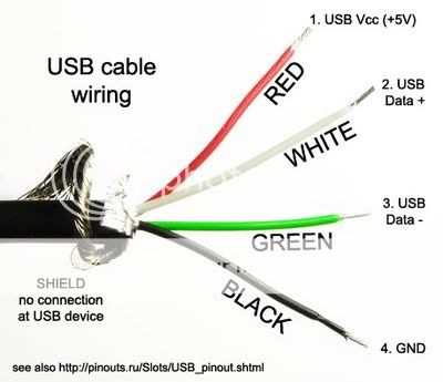
I hacked a USB wire

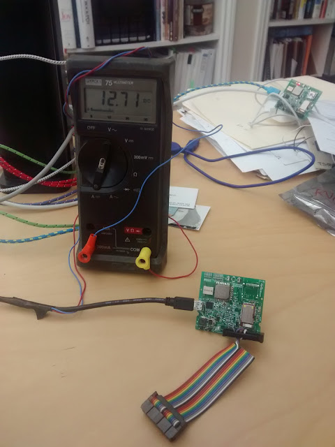
and inserted my Fluke ammeter into the red wire.  Could I somehow screw this up?

Then I configured the system simply to scan for BLE traffic continuously.  The results are not encouraging.

I guess the next step is to do a lot less, and try to figure out where the power is going.

David:


I got the board loaded and running and a 0.05 ohm resistor installed at R1001. All of the Nordic current should go through that resistor. I measure 0.124 mV, so 2.48 mA during MAIN SCAN_STARTING and briefly (maybe half a second) a much higher current of about 34 mA, I guess during MAIN SCAN_STOPPING. It’s too short to measure accurately with a meter and I haven’t hooked up the scope yet. The 0.05 resistor might make a voltage too small for the scope. Well, it *is* too small for the scope’s minimum range. A 0.5 or even 1 ohm resistor would be better.
I’m pretty sure about the 2.48 mA measurement. At least it’s not 12 mA.
11:27 PM (6 hours ago)

I was going to measure the total current but I don’t remember the function of the jumpers on the board to bypass the regulators and I need to go to bed. I can say that the FT232R is drawing about 1.94 mA.