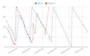
Following our discussions I had a poke around the Freestyle Libre.
I discovered that I could export data from the PC app to a spreadsheet.  The format is as you might expect – very obvious.
I also futzed around trying top read an old sensor (I read that you can break them somehow – seems unlikely, but…)  After a bit of fiddling around I finally managed to get the sensor to spit out something to my Android.   Now I need to figure out the format.  
I know from reading around that the fields contain:
  1. the time and date of reading,
  2. the time (and date?) the sensor was activated
  3. the reading #
  4. BG reading – probably in  mmol/l
  5. a flag indicating if it was a 15m scheduled sample, or a user initiated sample


Ultrasonic Wake-up device (Results)

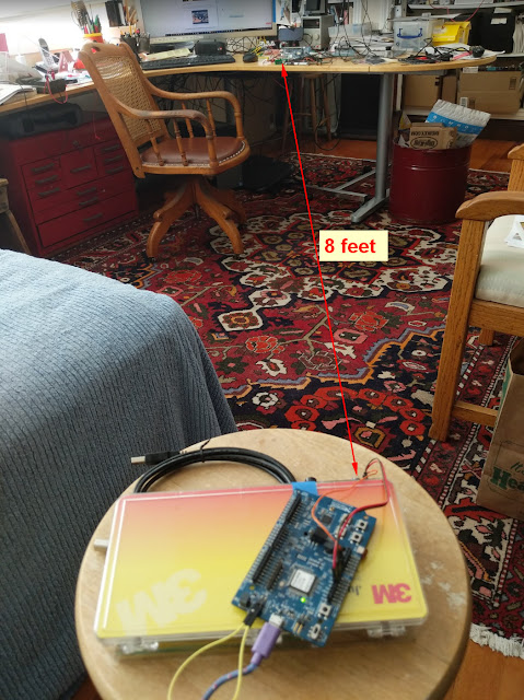
I’m getting to the point of diminishing returns on my ultrasonic wake-up device.  I have fiddled with transformers, different transducers, and filter components.  It works, but pretty much as I expected, the results are not great.  The maximum range is about 8′, and the transducers need to be perfectly aligned at that distance.  There is in bright sunlight.  Clearly this is not going to work with a device that might be up a sleeve.  
I knew I was optimistic in thinking that it might work.  I have to remind myself that it was a great learning experience, and I should recap what I achieved so I feel better.
  1. I found some circuits online and butchered them to meet my peculiar needs.  In particular I designed everything around the lowest operating current comparitor I could find (and understand)
  2. I actually built a transmitter and receiver which are clearly the most complex things I have built, and are all analog which is so much harder than digital stuff.
  3. I designed a PCB for the receiver, and only made one mistake – though it was kind of fatal – leaving off a critical wire.  I guess there is some way to check out designs to make sure they are all fully connected.
  4. I figured out how to solder, and more importantly de-solder stuff using David’s hot-air gun.  That’s a really useful thing to buy.
  5. I debugged the two devices using the scope.  I figured out how to generate an FFT so I could make guesses about the source of the unwanted noise.
  6. I figured out how to make an appropriate low-pass filter to get rid of all the MHz crap, the source of which eludes me.
  7. I wrote transmitter software for an nRF52 to send a 40kHz (sine-ish) signal to the transducer using a couple of transistors in push-pull mode.
  8. I wrote receiver software to listen out for a signal, and reset the comparitor if it heard a signal.

Range and reliability demo

The transmitter wakes up every 2 seconds and sends a sequence of 20  u/s “wakeup” pulses. 
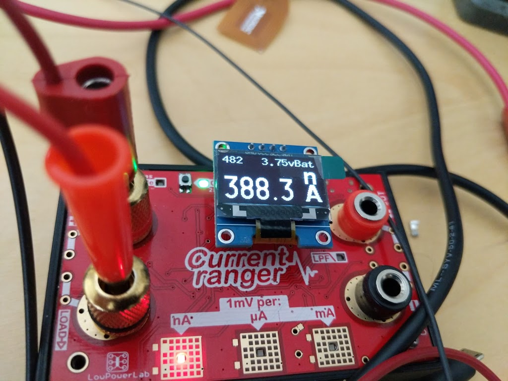
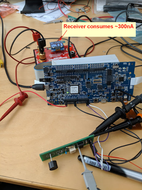
The nRF52 receiver is normally in deep sleep consuming 400nA.  When a u/s pulse is detected my receiver raises a GPIO and the nRF52 resets(reboots).  All it does is flash an LED and go back to sleep..

Discovery

The transformer is adjustable.
Useful explanation.

Measuring sleep current nRF52840

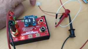
I finally managed to get a reliable measurement of sleep current on the NRF52840 DK
https://studio.youtube.com/video/aNdvIg-eLKE/

The code should not be run in debugger mode.
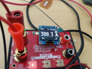
YAY!  ~400nA

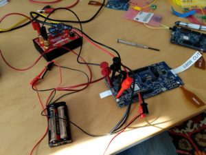
This setup puts the current ranger in series with the PSU connected to P21.

The setup was too complicated.

It was necessary to cut a trace and use two PSUs – well a battery and a PSU.
N.B. The “Preview” DK doesn’t work because it doesn’t have a special place SB58 to cut the trace.  So that clearly was a source of some weeks head-scratching.

I connected the bench PSU to P21 and supplied 1v8.  

It was also necessary to connect a separate supply to the interface side of the board.  I connected 3v3 between ground and Vdd.  This voltage must be higher than the supply on P21.  That was the special sauce.
Other details.
SW10 “Vext to nRF” has to be set to ON
SW9 has to be set to Vdd
If SB40 is cut then jumper P22 has to be in place.

This is a simpler setup

  • nRF52840 DK not preview version!
  • External PSU connected to P21
  • Current ranger across P22
  • Switch vEXT->nRF OFF
  • nRF Only/Default switch on nRF Only

Latest setup
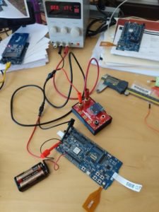
Connections
  • Power comes from two sources: the bench PSU, and a 3V battery pack.
  • The Current Ranger is in the +ve line of the bench supply which feeds the “External” connector
  • The battery is between the ground of the bench PSU and the Vdd pin on the nRF52 because it needs to fool the current tracker.
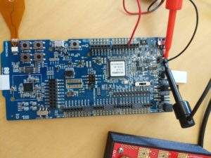
Switches
  • Switch SW6 is on “nRF ONLY”
  • Switch S10 is “ON”
  • Bridge SB58 is cut
  • nRF power source switch is on Vdd
  • p22 is bridged with a jumper IFF SB10 is cut
I don’t see a point in using a super-cap for energy harvesting apps.  May as well use a lipo, which has better power density.

Slow charge a LiPo from harvested power

For battery charging purposes maximum power-point tracking seems to be a good thing.


Looking at the energy harvesting regulators that David found they seem to be specialized for different applications:

Thermoelectric Regulators

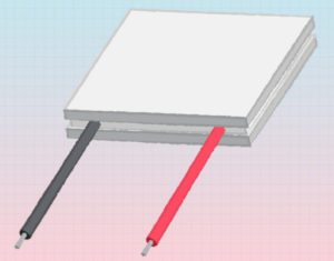
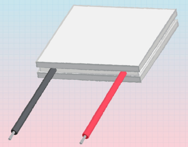
I am assuming that the options here are a Peltier, or a thermopile.  I have not seen a thermopile that even approaches wearability, so I’m going to assume that a Peltier is the only feasible wearable device.

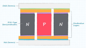
This is an article about Peltier modules that I can understand: https://www.cui.com/blog/how-to-select-a-peltier-module.   Unfortunately it only deals with the case where the Peltier is used as a heat pump, not where it is used as a TEG.  

Using it backwards to generate electricity is called the Seebeck Effect.  From the examples on this video it looks like you need fire on one side, and ice on the other to generate enough current to charge a phone!
Here’s a 12V Peltier plate spec

Model: TEC1-12706.
Size: 40mm x 40mm x 3.6mm.
Working current: 4.3-4.6 A (rated 12 v); Imax: 6A.
Rated voltage: DC12V (Vmax: 15 v starting current 5.8 A).
Operates Temperature: -30℃ to 70℃.
Refrigeration power: Qcmax 50-60 w.

They come in sizes as small as 15x15mm from Digikey.

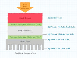
Have to get good contact between the heat source/sink and the Peltier.  Here’s some heat conducting glue.  Also probably need a heat-sink.

Digression – Peltier watch…

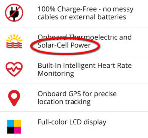
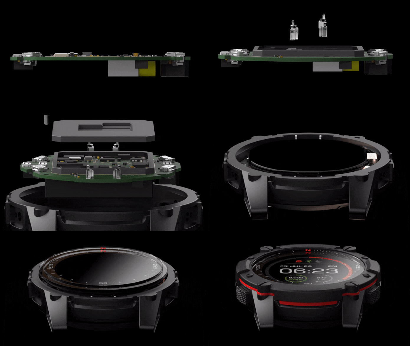
Here is a proof-of-concept Peltier watch which at least shows it’s feasible.

Latest update is not great news.   I wonder how often you have to get your wrist out in the sun to be effective.

Cool Video – https://www.indiegogo.com/projects/smartwatch-powered-by-you-matrix-powerwatch-2#/
I wonder where the solar panel is?

Back to the plot…

So the other thing I might consider is placing a Peltier atop a radiator, or somewhere where it would gather direct sunlight.

LTC3106
LTC3107
LTC3108-1
LTC3108
LTC3109
ADP5091

ADP5092

Piezo

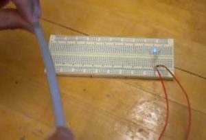
Piezo seems easily capable of illuminating a LED with a relatively small force, deflected over a significant angle.   Here’s a crappy quality video, but the demo is really simple and obvious.
LED illuminates momentarily each time the piezo strip is flexed
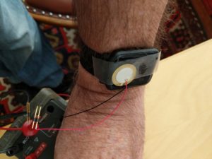
I decided to do my own experiment with some stuff I had to hand.  Suppose I wanted to harvest some energy from a wearable.  What sort of piezo could I use?  Would need to be small!  I got a piezo beeper that I salvaged from somewhere, and simply taped it to my Bip watch.   
Then I attached a voltmeter to it and walked up and down.., viz.

On the 300mA setting I got nothing, so I guess uA is the best case!  I connected the currentRanger and got a tiny nA reading which I assume was AC hum.  I stuck a diode on one terminal and tried again.  By tapping the piezo pretty hard with my finger nail I managed to see a peak of 16nA.  16nA at 40mV… hmm?
So I’m not all that encouraged by this either.

Solar

Solar seems like by far the most encouraging.  The question is how much energy can be generated behind a window.  I know that window glass attenuates the received energy very substantially.
ADP5092

Slow charge a supercap

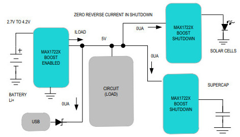
Here is an app schematic that seems to handle both solar and capacitor.

Quick Charge

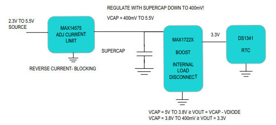
And here is one designed just to charge a cap.


But the MAX14575 requires that the input voltage is the same as the desired output voltage.  Also it seems to have some limit on the size of capacitor it can handle.

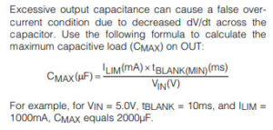
For a 100F SuperCap    100,000,000 = (250 * tBlank) / 2.7.  
tBlank = 1080 seconds!

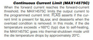
So it seems like it will turn the output on/off until the overcurrent condition goes away.  The duty cycle will be about 3%.  The alternative is to use the 14575C which does not duty cycle, but it might get hot!


 The MAX667 seems to limit the voltage and the current (to 250 rather than 240, but hey).  But perhaps it doesn’t limit the current drawn, and simply get’s hot and angry.
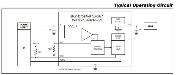
I found two ICs that might be able to limit voltage and current.  There are probably others.
I need to see if they can limit voltage to 2v7 and current to 240mA.

MAX17525

I don’t really understand what this does.  It seems like it simply limits current, and not voltage, and the current limiter seems to high.

MAX14575

The MAX14575A/MAX14575AL/MAX14575B/MAX14575C programmable current-limit switches feature internal current limiting to prevent damage to host devices due to faulty load conditions. These current-limit switches feature a low 32mI (typ) on-resistance and operate from a +2.3V to +5.5V input voltage range. The current limit is adjustable from 250mA to 2.5A, making these devices ideal for charging a large load capacitor as well as for high-current load switching applications.
This too only limits current and not voltage.  So it looks like I will have to use a regulator to get the voltage down to 2v7.
I see there are regulators called LDO (Low Dropout) the benefit of which I don’t understand.
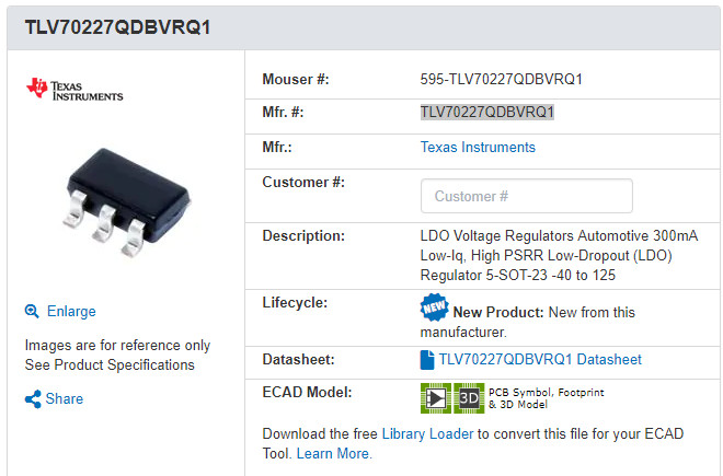
But here’s a Texas Instruments regulator that will output 2v7 upto 300mA.  Perhaps I need to be able to produce more than that to make sure the current limiter can generate enough?  Anyway 300mA for now.

TLV70227QDBVRQ1  looks like this.


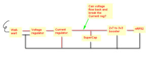
So basically, I’ll have the LDO sucking 5v5 and blowing 2v7 at 300mA into the current limiter which will pass through 2v7, but chop the current at 240mA (10C).

Now my question is, do I really need the current limiter, or can I rely on the LDO to limit the current, or does it catch fire if the supercap tries to draw too much?

SuperCap Feasibility

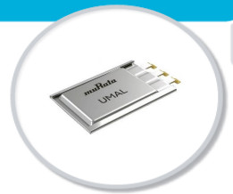
I’d like to start by seeing how much I can get from a supercap.  This seems to be one with a reasonable capacity, and a decent shape for a wearable – although sadly it isn’t curved.
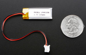
The SuperCap is (14x21x3.6mm) ~ 1058 mm3.   The LiPo below is Size: 11.5mm x 31 x 3.8mm ~ 1355 mm3
LiPo:     11.5*31*3.8/105 =  13 cu mm / mAh
SupC:   14*21*3.6/24 = 44 cu mm / mAh
So the SuperCap is about 30% of the energy density.
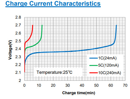
At the maximum 10C charging rate which is 240mA it takes about 6 minutes to charge up.
Discharge is fairly flat for about 55/65 = 85% of the time.  After that it dips away quickly.  So let’s assume that there are 24 * 85% mAh in the SuperCap.
I assume I need a boost regulator to get to 3v3, or a buck regulator to get down to 1v8.  Running at 1v8 means logic-level converters to talk to some sensors.  A booster will waster 5% of the energy at best.  I’m not sure what is a reasonable estimate.  Let’s say 10%.  
So now we are talking about 24 * 0.85 * 0.9 which is 18mAh.  So I wonder how many hours I can listen on BLE with 18mAh to spend.

The Amazon BiP sports a 190 mAh battery. Our data shows that it can listen for BLE packets for at least 10 days.  It’s also running sensors, a display, and a GPS periodically.

So its sucking 190/10 mAh per day = 19mAh / day

So a supercap is in the ballpark.  Maybe with an e-ink display it can do better.

Charging the SuperCap

The SuperCap can only be charged at 2v7 max (?).  And the maximum current it can handle is 10C which is 240mA.  (Does that mean fat traces?)
Given this will be charged initially from a regular 5V USB PSU (I assume) then there needs to be something to limit the current, and voltage.
I know I can limit the voltage with an ordinary regulator, but this needs to limit the current too.  
MAX17525 , or MAX14575 seem like they might do the trick.  I suppose there are lots of contenders.  These are the first I found.  

I’d like to make a PSU that can try out a whole bunch of charging strategies:

‘Instant’ charging.

Instant = seconds to minutes.
Scavenging

Getting energy from light, heat, wireless, movement, RF, and anything else that seems interesting.
Objectives
An anchor node running 24×7 with no maintenance required.
A wearable that can either scavenge power, or needs a few seconds recharging each day.
Can this be tried out with a single desktop prototype?