Lift your spirits everyday on Imgur: https://m.imgur.com/r/DIY/FSBwD3g
|
 Fri, May 17, 4:32 PM (19 hours ago) Fri, May 17, 4:32 PM (19 hours ago)
|
|
||
|
||||
Knocker-Upper Service (KUS)
Family History
I dimly recall my Mum telling me that someone in the family was a “knocker-up”, or “knocker-upper”. This was in a time before inexpensive alarm clocks, and so getting to work on time was a challenge, especially if you had a physically tiring job, or were a regular attendee of the pub. Being late for work carried serious consequences, which might mean pay being docked, or simply being dismissed. It also produced the joke about “knocking up whole streets before breakfast”.
Workers lived in row-houses (like Kismet) where the front wall of the house adjoined the pavement (footpath), and the main bedroom was upstairs at the front. Because the houses were small, the sleeper’s ears would be but a yard or so away from the window. So the knocker-up would tap on the upstairs window until they saw a face at the window. Tapping on old glass risks breaking the glass which would be a major expense, and annoyance – especially in the winter. So many knocker-uppers had a long pole with some sort of ‘tickler’ on the end. It was just enough to make an irritating noise on the window, but with much less chance of breaking the glass. In return for waking the client, the knocker-upper would receive a few pennies per day. If the worker failed to make it to work on time, the income streams of both knocker and knockee might be terminated, so the knocker-up was motivated.
https://en.wikipedia.org/wiki/Knocker-up
https://vimeo.com/album/3066233/video/108109027
What’s this got to do with WUR?
The objective with a wearable is to save power whenever possible by switching the uC off. A typical approach is to wait for some external signal – typically a wireless signal, or an interrupt generated by an attached sensor, or a clock. Listening for a wireless signal consumes power – perhaps a few mA. Keeping a sensor running consumes power too. Even a few-hundred microamps consumed over hours, days or months mounts up. Quite a small battery can listen out for several months or even years, but the battery adds substantially to the size of the system. It is often the case that the size of the device is compromised by the battery size.
One approach is simply to hibernate the uC completely so that the current it consumes is basically just a few hundred nanoamps. Then the the process of waking up, the equivalent of pressing the ‘boot’ button, can be delegated to some local service that has the means to wake up the uC – a “knocker-up service”.
But even then, if no “knocker-up” service is available, then you are on your own, and have to monitor conditions (clock, activity, radio-input) yourself.
Knocker-up service System concept
 |
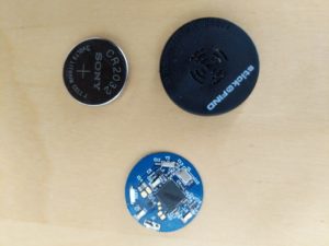
| How KU services are deployed |
A knock up service is a wireless service that can be used to wake up a hibernating client. We assume this service has a constant source of power. It is assumed that the client has entered a mode where it is using little, or no power so it doesn’t have the wherewithal to rouse itself. However the KUS can radiate energy, and the client has an antenna large enough to scavenge enough energy from the radiated radio signal to jump-start itself. After that point, the client has to use whatever resources it has to hand to determine why it has been woken up, and to act accordingly.
When a client knows is ready to hibernate, it uses some means (BLE perhaps) to check to see if there is a KUS nearby. The KUS service sends a ‘rehearsal knock’ to make sure that the client is able to hear the knock-up signal. If the client receives the test knock, then it can contract with the KUS to be reactivated under whatever conditions the KUS is willing to offer. A simple example might be, “In 10 minutes”.
A more elaborate, but perhaps more useful case is when the client wishes to go to sleep until some third-party service wants to communicate with the client – to send an alert of some kind. Before going to sleep the client might contact the alert service, providing two bits of information: the IP-address of the client’s KUS (it’s proxy); a secret number that has been previously arranged with the particular KUS. When the alert service decides it needs to wake up the client, it sends a wake-up request to the client’s proxy (the particular KUS), together with the previously shared secret. The KUS checks the secret is valid, figures out which client it should wake up, and sends the wake-up event.
In the simplest of all worlds, the client wakes up and has to check in with the KUS to find out which of perhaps many services, has tried to get in contact. Then it is on it’s own to contact the specific service and finish business.
If the client fails to wake up, then perhaps the KUS retries a few times, but finally logs the attempt, and then gives up.
In a more complex implementation, the KUS might share the wake up request with a few geographically proximal peer-KUS services to see if they can wake up the client.
Enclosure ideas
My objective was to create a wearable enclosure for the peculiar set of gubbins I want to use. Appearance is not the main priority, so if it looks a bit rough that’s OK, and can be left for a time if/when the thing works. On the other hand it needs not to break and spill its guts on the street. I can always print a new enclosure if the current one is wearing thin.
My original enclosure ideas were a bust for one reason or another.
Bangle
The fixed-size bangle idea was aimed at making something that was very easy to put on, and take off. There would be no display, and I was thinking it would be glued together, and charged inductively. This certainly was an easy on/off design, but it was really hard to get a good fit.
I tried a whole bunch of ideas and the best was the following:
Likes and Dislikes
The parts fitted together tightly, and I’m sure with appropriate glue would be strong enough. The opening was too sharp and scratched. The curve did not transition smoothly at the top from one side to the other.
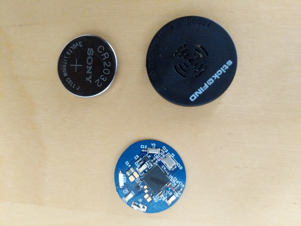
There seemed to be enough room for a pretty large battery, and a non-flexible board with nRF52 and DecaWave module + accel.
It was certainly workable for a first prototype, and could probably have been made from some material that looked less obnoxious.
Of course it didn’t have a display, and was rather thick. A lot of the problem is that, being conservative about power, I selected a big battery. The other problem is that I only know how to make a non-flexible PCB, so there’s a lot of wasted space. Not shown is the vibrator motor.
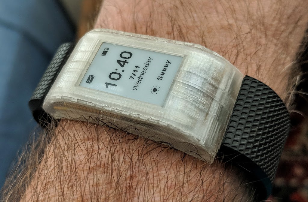
Watch with off-the-shelf strap
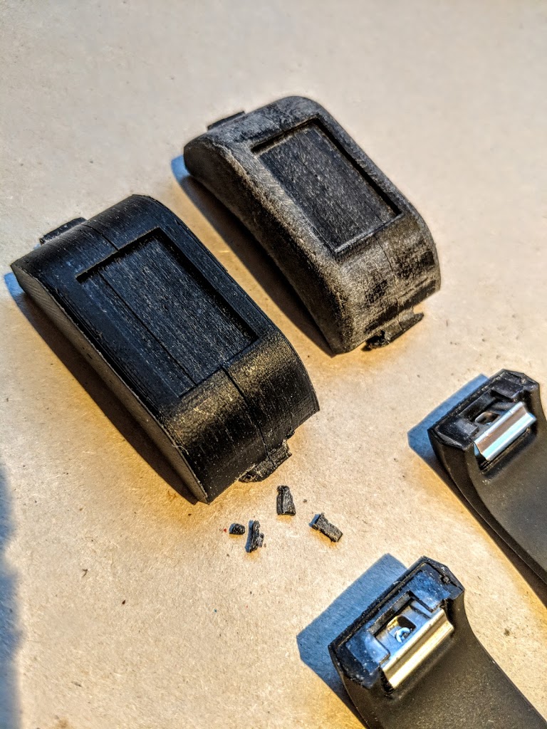
This was a plastic case that could hold an e-ink display as well as the other large components. This version uses an off-the-shelf Fitbit watch strap.
|
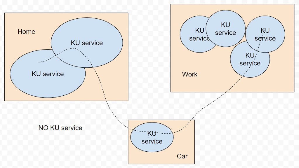
| With strap attached, but no display |
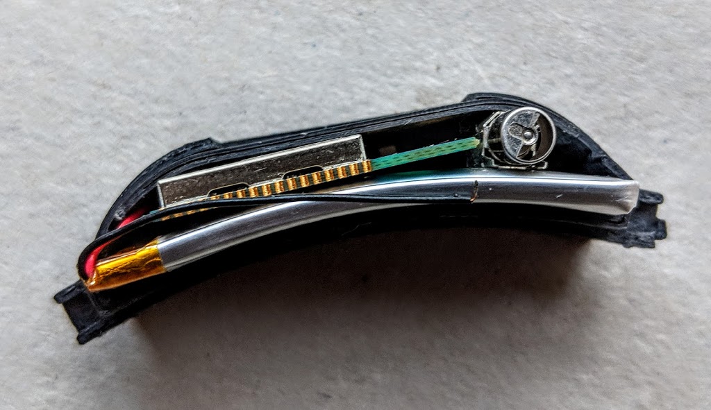 |
| Battery, uC and vibrator installed |
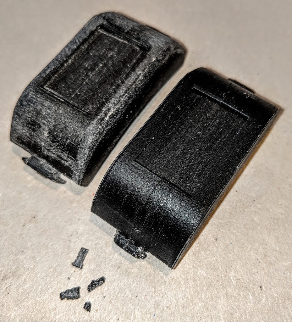
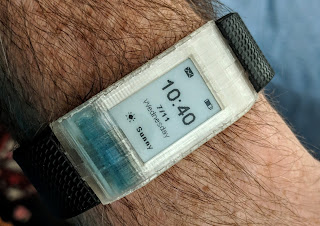 |
| Assembled, but of course – non-operational |
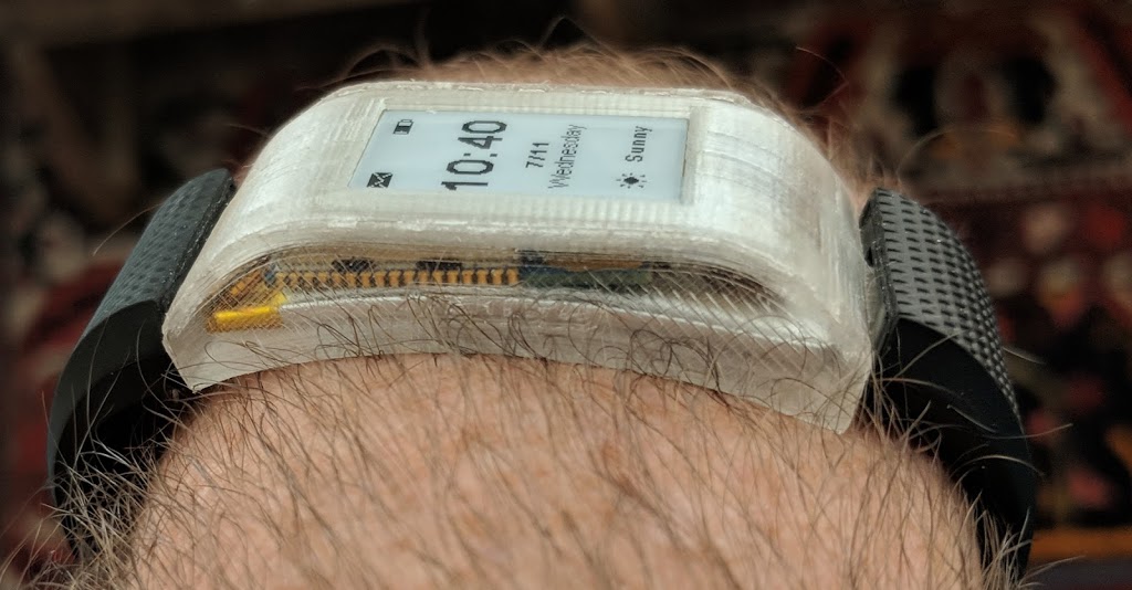

I was rather pleased with progress on this version because the strap actually held the two parts together which would be great for test before it was finally glued.
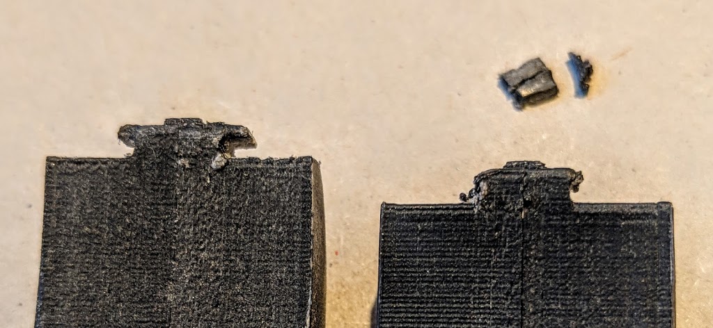
The major show-stopper was that lugs for attaching the strap were way too brittle, and would snap off at the least provocation.
So what now?
The e-ink display has a lot of power advantages. The strap mechanism is cool, but clearly not strong enough. So I probably need to run with the same set of components, but perhaps I can use a smaller battery if I can figure out a wake-up radio of some sort.
Some brain fodder
Lamming Mouse circa 1974
 I had grown up creating programs on punched cards, or paper tape. It was very exciting when I got to use a time-sharing system. The ‘new’ way to interact was using a teletype. A teletype could output 10 characters/second onto a paper scroll. This was not that unreasonable given the time it took for the computer to respond to a command. Some days, you could type a line and wait many minutes, perhaps 20, for a response. One of the cultural side-effects of this was that we lowly beings used to go use the computer at night. Computers always ran faster at night in those days.
After I graduated, I stayed on to do some research, and joined George Coulouris’ research team who lived in a converted college theater called Stern Hall. We had one computer, an Interdata Model 4. It did not run faster at night because it was a single-user machine. Tony Walsby has written amusingly about this period. However, nothing much changed for me. Students were low in the pecking order and could only get useful slots of time at night.
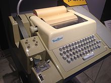
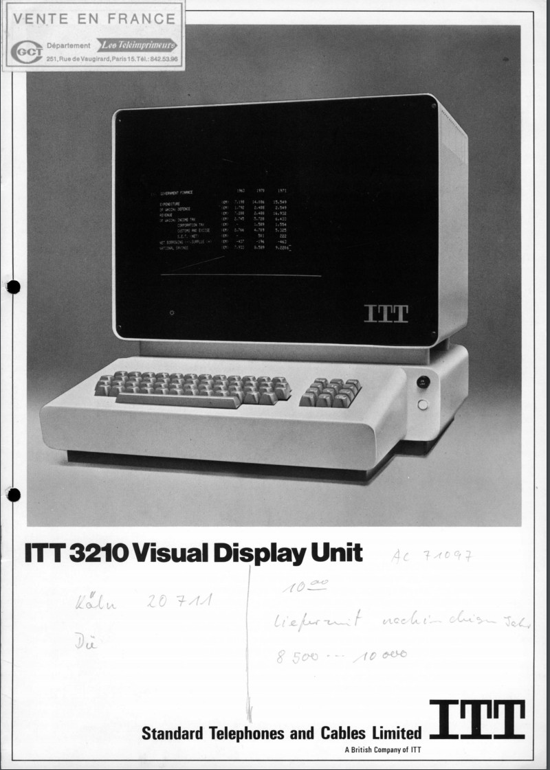 |
| ITT 3210 |
Sometime around 1972 we got our own time-sharing system which ran Unix on a PDP 11/40. This was a fantastic improvement in some ways, and worse in others, and marked the time I got my first email account. Our time-sharing system still had an unpredictable response time, but you could “get time” on them more easily.
What was especially wonderful was that we didn’t have to use clunky teletypes. We had about 6/8 “glass teletypes” aka “dumb terminals”. Each of these ITT 3210s was connected by 9600baud wires to UNIX. The screen displayed an 80×24 (?) grid of fixed font characters with a few different faces. Theoretically the dumb terminal was almost 100 times faster than a teletype. But we still used them in a very simple way as a “glass teletype”.
One day I was talking to an engineer who had come to fix a broken 3210. It was late in the day, and we got chatting, and he told me something that caught my attention. Apparently it was possible to send special ‘escape’ characters to the terminal that would allow you to write a character anywhere on the screen. This was well known in the UNIX world, but not so well in Stern Hall. We didn’t yet have the special driver upgrades to use them in a cleverer way, but I think Richard Bornat, or Jon Rowson eventually took care of that.
So I got to thinking what life would be like if you could write stuff anywhere. Having been told that the airline booking systems had created a form-filling kind of UI, I got to playing around to see if I could divide the screen into several smaller screens. I have to confess that I was thinking that I could have multiple streams on interaction running at the same time, instead of the usual one – which meant I could probably hog more of the machine time. I started by partitioning the screen, but soon found that I could simulate overlapping terminals.
 |
| Text Terminal (hand on mouse) |
I recall that I actually managed to hack a system with 2/3 overlapping terminal areas, which looked terrible, but kind of worked. I showed to Jon Rowson. Jon, who was really smart, got fired up and spent a year or so building a complete window system using the same principle. It was used for a whole bunch of projects. Switching the input focus between windows was clunky. You either had to tediously move the cursor to the target window using cursor keys, or had to cycle through all the windows using a special ‘next-window’ key. Most systems just used a couple of windows.
At about this time, Mike Cole started a project to build a terminal that would do this overlapping windows thing properly. He and Tony Walsby built the Text Terminal. It seemed very cool, and I wanted to redo my multi-window thing on it.
Moving between windows was still a pain, and Tony had implemented a joystick to make it easier. I had fiddled with a trackerball idea, which I thought was better because you could scoot it fast to move fast. I actually started work on a tracker ball, but it soon became clear that it was a lot easier to use if you turned it upside down and rolled it across the desk to re-position the cursor. Of course the cursor had to move in the opposite direction, but it seemed to work well.
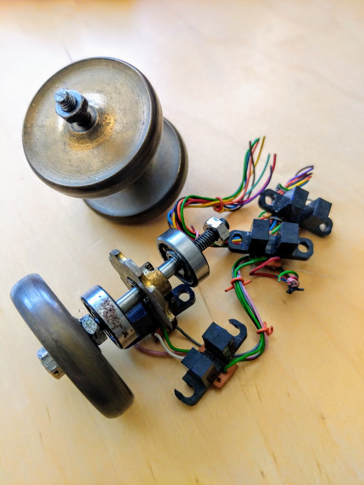
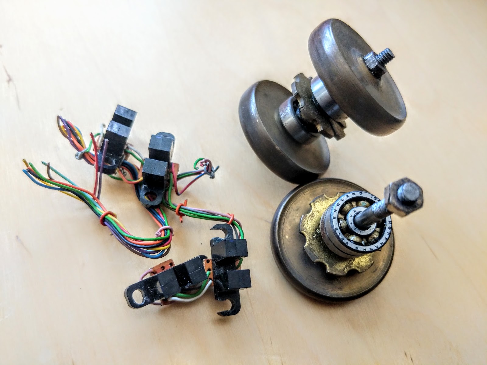
So I decided to build an upside-down tracker ball, using wheels and some home-made shaft encoders. The wheels were turned up on a lathe from brass rod. The shaft-encoder (a rather superior description for what it was), was a Mechano pulley wheel – filed down to be small enough, through which the light from an interrupter could shine. The whole lot was stuffed in an off-the-shelf plastic box, had a few buttons added, and was used to actuate the appropriate cursor keys on the Text Terminal (I think Tony did that bit). Against all expectations, it worked amazingly well, but was very heavy. You could get insured if you dropped it on your foot. Someone later made a furry cover for it with eyes, ears and whiskers.
The other day I was cleaning out my boxes of junk and I came across the gubbins. It made me laugh to see it again, and see the very variable standard of workmanship.


fossmint.com: CloudReady: How to Install Chrome OS on Any PC. https://www.fossmint.com/cloudready-install-chrome-os-on-any-pc/