Measuring sleep current nRF52840
I finally managed to get a reliable measurement of sleep current on the NRF52840 DK
https://studio.youtube.com/video/aNdvIg-eLKE/
https://studio.youtube.com/video/aNdvIg-eLKE/
The code should not be run in debugger mode.
 |
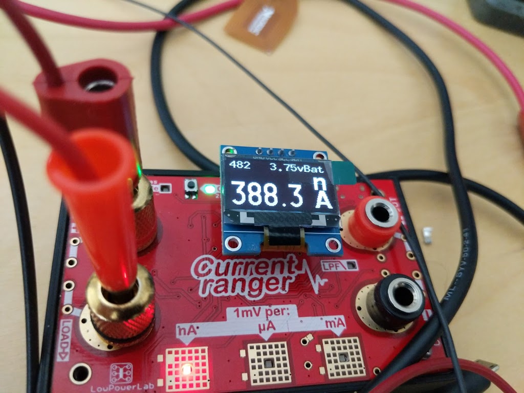
| YAY! ~400nA |
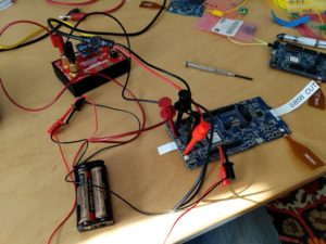
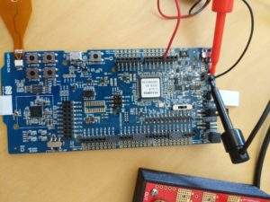
This setup puts the current ranger in series with the PSU connected to P21.
The setup was too complicated.
It was necessary to cut a trace and use two PSUs – well a battery and a PSU.
N.B. The “Preview” DK doesn’t work because it doesn’t have a special place SB58 to cut the trace. So that clearly was a source of some weeks head-scratching.
I connected the bench PSU to P21 and supplied 1v8.
It was also necessary to connect a separate supply to the interface side of the board. I connected 3v3 between ground and Vdd. This voltage must be higher than the supply on P21. That was the special sauce.
Other details.
SW10 “Vext to nRF” has to be set to ON
SW9 has to be set to Vdd
If SB40 is cut then jumper P22 has to be in place.
This is a simpler setup
- nRF52840 DK not preview version!
- External PSU connected to P21
- Current ranger across P22
- Switch vEXT->nRF OFF
- nRF Only/Default switch on nRF Only
Latest setup
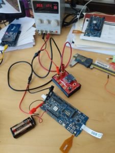 |
| Connections |
- Power comes from two sources: the bench PSU, and a 3V battery pack.
- The Current Ranger is in the +ve line of the bench supply which feeds the “External” connector
- The battery is between the ground of the bench PSU and the Vdd pin on the nRF52 because it needs to fool the current tracker.
 |
| Switches |
- Switch SW6 is on “nRF ONLY”
- Switch S10 is “ON”
- Bridge SB58 is cut
- nRF power source switch is on Vdd
- p22 is bridged with a jumper IFF SB10 is cut
