Scroll down to the “FlashAir 3rd attempt – success at last”

Attempt #1 

I found the SD card annoying.  It was easy to flip the “locked” switch when inserting or removing the card from the reader.

Solution (not)

I bought a FlashAir SD card.  This is an SD card that has a WiFi interface.  The card can be left installed and loaded/uploaded with files over WiFi using a web interface.
The device fails both from a software, and a hardware standpoint.  It’s a shame because it would be really neat if it worked correctly.
It is intended to be used in cameras that don’t have wireless, so that they can upload pictures to the web.   So using it to download gcode files is conceptually a small difference.  I found examples of people who use this card on their 3D printer.
It takes a bit of fiddling to set it up, but even though this was a bust I am recording the process.
The card has to be initialised using software downloaded from here:
In fact I suspect that it isn’t necessary to use this software unless the card needs re-initializing.

Configuring

Configuring the card to work as I desired was simple but very obscure.  After trawling around on the web for a while I discovered that the configuration is fairly simple.  
Once the card can be made visible to a computer, it might be necessary to change the properties of the card so that all the files are made visible.  
A file called “CONFIG” will be found, and should be set up as follows.

[Vendor]

CIPATH=/DCIM/100__TSB/FA000001.JPG
APPMODE=5
APPSSID=mb8
APPNETWORKKEY=<mb8_password>
APPNAME=prusa
UPLOAD=1
UPDIR=
VERSION=F15DBW3BW4.00.03
CID=02544d535736344755f459227b012501
PRODUCT=FlashAir
VENDOR=TOSHIBA

Once the file has been saved the card can operate stand-alone.  I actually simply plugged it into a PSU to test that it would work stand-alone.

Because my APPNAME=prusa I was able to find a web-site called http://prusa
Uploading files to the card was clumsy.  You have to type in another URL: http://prusa/upload.cgi
I guess this would have been just about OK.  The UI is about a simple as it can get.   You use the “Choose File” button to select a file, and the “submit” button to upload it.
It’s so quick that it feels like it failed!
When the upload is complete it completely confusesd me by displaying the following.
So I uploaded a bunch more to make sure I wasn’t being a dummy…
However when I went back to the directory listing mode I found this:
I found that although I could access the card if I pushed it into the SD card slot of my laptop, I couldn’t access it using USB plug-in devices as shown in my photo above..  So connecting to the desktop machine was out!  
Plugging the card into the Prusa I found that I could indeed download files OTA to the card.  Yay!
However the card does not function as a viable SD card when plugged into the Prusa.
The card is capable of powering up, and displays some kind of directory structure.  
Sadly there only entry in the list that does anything is “Back”.  The directory entry does sweet FA.

Possible reason for problems

My FlashAIR card is SDXC (64GB) and I suspect Prusa only accepts the old style SDHC (up to 32GB).  The new format uses the exFAT file format, and I’m guessing Prusa expects FAT.

FlashAir Setup 2nd attempt – TBD

GitHub – FlashAirDevelopers/FlashAirFileManager: The application to browse and download files on FlashAir™ via the network.
https://github.com/FlashAirDevelopers/FlashAirFileManager – XXX deprecated

FlashAir 3rd attempt – success at last

  • I bought a 32G W04 card.
  • All the setup programs etc are useless, unless you have to re-init the card.
  • Plug the card into a computer that has a card reader, and use a text editor to edit the file: CONFIG

This is the right stuff to put into the file

[Vendor]
APPSSID=
<your-wifi-name>
APPNETWORKKEY=<your-wifi-password>
CID=02544d535733324740e35b5979010b01
VERSION=FA9CAW3AW3.00.01
APPMODE=5
APPNAME=Prusa
LOCK=1
PRODUCT=FlashAir
STA_RETRY_CT=0
UPDIR=/<Directory name to put G-Code>
UPLOAD=1
VENDOR=TOSHIBA
WEBDAV=2

  •  Save the file, and wait 10s.  Do not safely eject the card.
  • Now make a network drive:

Should be able to drag and drop GCode files onto the card.
NOTE that Prusa only shows files with the “.gcode” or “.gc” extension

  • Now can go to Prusa find the file and print it.
Some more documentation


Update 10/17/2019

Here are some useful words on cooling parameters.

It’s all about getting the right parameters. (10/9/2019)

First job, download the manual.  All the relevant stuff was here.  https://www.prusa3d.com/drivers/

Next, download the slicer and firmware.

Install the slicer “slic3r”

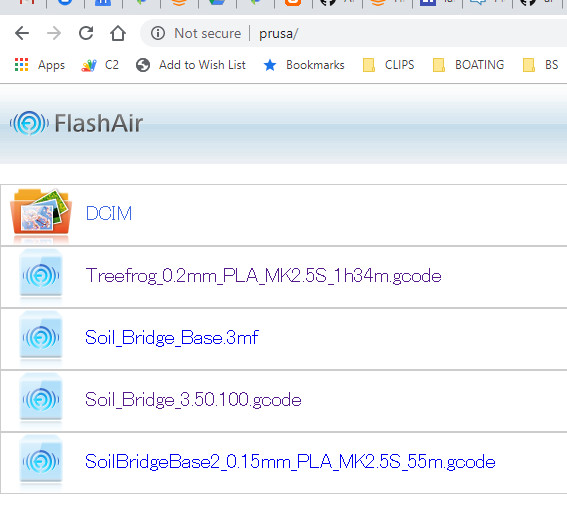
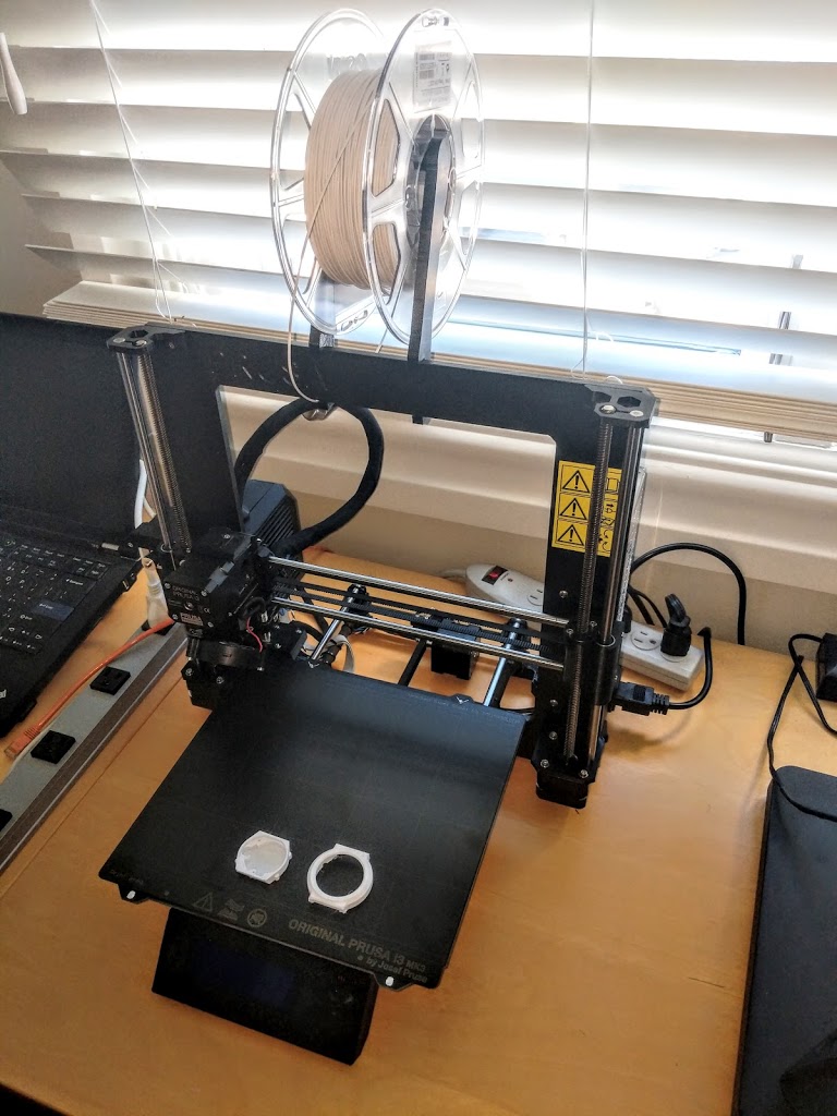
Ran treefrog I downloaded from itnernet before I realised that Prusa use the same model 🙂

Prusa reports that it needs new firmware

Thermal Runaway during printing!   Better install new firmware.

Download firmware, and install manual
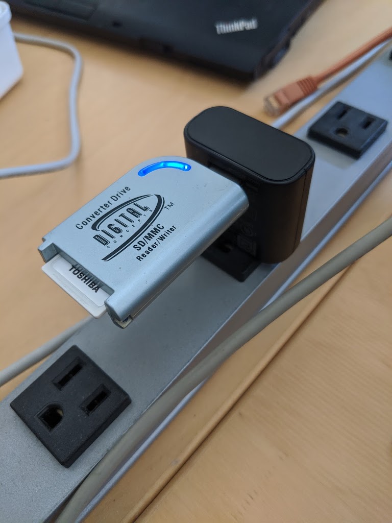
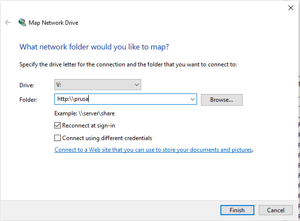
Connected printer USB to PC
Printed the upgrade instructions.  Reference to Slic3R PE which doesn’t seem to be part of the release.

Better instructions here https://help.prusa3d.com/article/r5ByKgVm69-firmware-upgrade-and-flashing.
Although the COM port shows up, the printer needs to be switched on.  Duh!

Tried again – flashing failed.  Now the printer is unresponsive – no UI.  It also erports that it is a Prusa 2.5 now!  Did I somehow load the wrong firmware – checked… no!

< various read and write commands followed by this>

avrdude-slic3r: verifying …
avrdude-slic3r: 244050 bytes of flash verified

avrdude-slic3r: safemode: hfuse reads as D0
avrdude-slic3r: safemode: efuse reads as FD
avrdude-slic3r: safemode: Fuses OK (E:FD, H:D0, L:FF)

avrdude-slic3r done.  Thank you.

avrdude-slic3r -v -p atmega2560 -c arduino -P COM16 -b 115200 -D -u -U flash:w:1:C:UserslammingDesktopPRUSAprusa3d_fw_MK3_3_8_0_2684.hex:i

avrdude-slic3r: Version 6.3-20160220-prusa3d, compiled on Sep 16 2019 at 11:15:49
                Copyright (c) 2000-2005 Brian Dean, http://www.bdmicro.com/
                Copyright (c) 2007-2014 Joerg Wunsch


                Using Port                    : COM16
                Using Programmer              : arduino
                Overriding Baud Rate          : 115200
avrdude-slic3r: prusa_init_external_flash(): MK3 printer emitted incorrect start code: `echo: `
avrdude-slic3r: arduino_open(): Failed to initialize MK3 external flash programming mode
avrdude-slic3r: Could not open port: COM16

avrdude-slic3r done.  Thank you.

Power cycle doesn’t cause a reboot.  Should I remove USB cable?

Noticed a useful document https://help.prusa3d.com/article/gXdRubco3u-firmware-updating-flashing-problems

Contacted David to see if this is a 3Mk3.  No!!  It’s a 2.5S

[13:50, 10/8/2019] Mik Lamming: R u available to consult?
Is this a i3 mk3?
[13:54, 10/8/2019] David Carkeek: Sure! It’s an i3 Mk2.5S
[13:54, 10/8/2019] David Carkeek: The i3 has a 24V power supply, so the motors are faster and the hot bed heats better.
[13:55, 10/8/2019] David Carkeek: Also, the i3 has extruded aluminum rails so it’s sturdier.
[13:56, 10/8/2019] David Carkeek: The “S” upgrade was primarily new linear bearings.
[13:58, 10/8/2019] David Carkeek: The “2.5” upgrade was a new hot bed, magnetic surface, new PINDA probe and holder, new extruder and fan, filament sensor. This enabled some software improvements.
[14:02, 10/8/2019] Mik Lamming: OK, I’m having some minor issues. I tried to print the treefrog example. It got about 2m into the process and then stopped saying “thermal runaway”. UI dead. Had to turn off. Turned back on and it said “upgrade firmware”. That was my downfall. I thought it was a i3 Mk3 because that’s what it says on the bendy plate. Took me a while to figure out the instructions for firmware upgrades were wrong. Finally did an upgrade. Verified OK but then gave some gobledigook
[14:02, 10/8/2019] Mik Lamming: avrdude-slic3r: arduino_open(): Failed to initialize MK3 external flash programming mode

avrdude-slic3r: Could not open port: COM16
[14:03, 10/8/2019] Mik Lamming: OK, so that makes sense because it is a 2.5S
[14:03, 10/8/2019] Mik Lamming: Just tied to flash 2.5s and it failed. I’m going to reset everything and retry
[14:06, 10/8/2019] David Carkeek: There are two versions of the controller board and you need to be sure that you select the right one when you flash it. The same thing happened to me when I selected the wrong controller.
[14:06, 10/8/2019] Mik Lamming: OK – how do I identify the controller board?
[14:06, 10/8/2019] David Carkeek: The thermal runaway error happens with the new fan because the extruder cools down too much when it turns on and doesn’t have time to recover before the thermal runaway error kicks in.
[14:07, 10/8/2019] David Carkeek: Then newer firmware was supposed to partially fix the thermal runaway error by not requiring a ramp speed as fast as what was used before.
[14:08, 10/8/2019] David Carkeek: But I could never get it to work with the fan speed set at 100%.
[14:08, 10/8/2019] Mik Lamming: Do I need the Mk2.5 or the Mk2.5S firmware
[14:08, 10/8/2019] David Carkeek: 2.5S
[14:09, 10/8/2019] David Carkeek: There are two solutions for the thermal runaway problem. One is to put a silicone sock on the outside of the extruder.
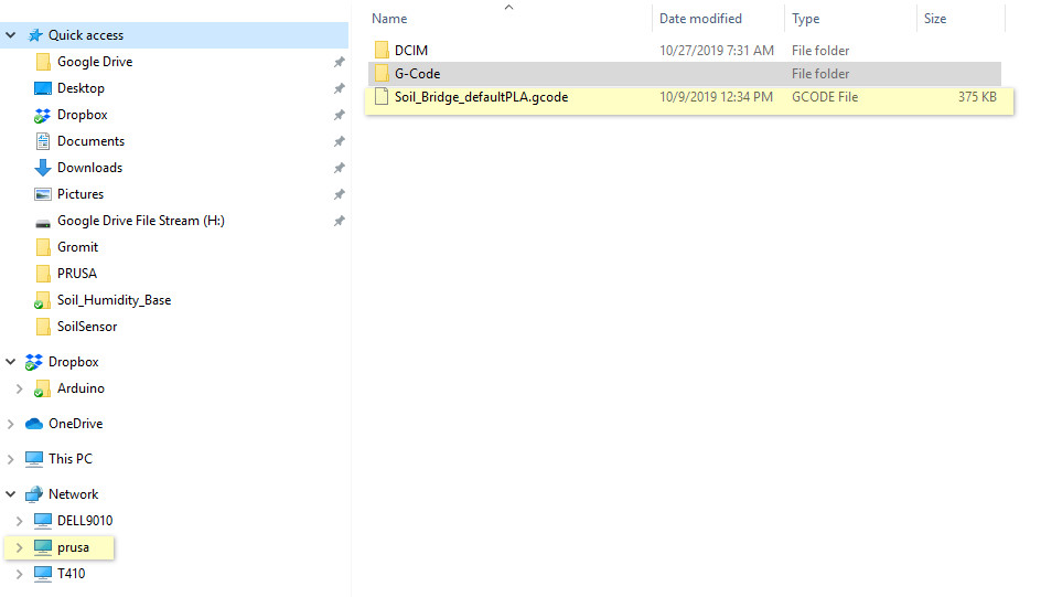
[14:09, 10/8/2019] David Carkeek: The other solution is to set the fan speed at something like 70%. To do that do you have to edit the G-Code.
[14:10, 10/8/2019] Mik Lamming: OK – good info.
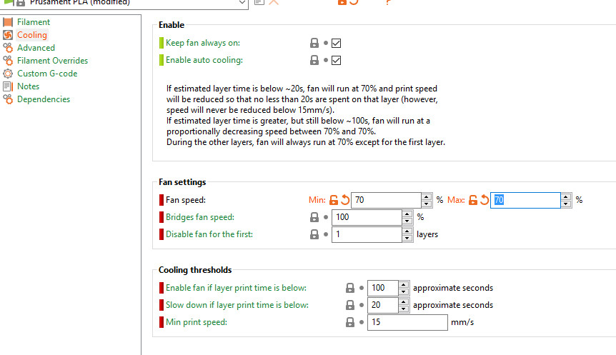
[14:10, 10/8/2019] David Carkeek: If y ou are making a new model there is an option to set the maximum fan speed in the slicer.
[14:10, 10/8/2019] Mik Lamming: There are dire warnings about not installing wrong firmware!! I wonder if I have done something dire.
[14:11, 10/8/2019] David Carkeek: For the question about the controller, I have to look. it’s obvious when you know what to look for and when it happened to me I was just careless and didn’t pay attention.
[14:11, 10/8/2019] David Carkeek: when it happened to me, I was sure that I had bricked to controller, but it seems to be pretty resilient and it was still okay.
[14:14, 10/8/2019] Mik Lamming: There is a document that shows the controller types.
[14:14, 10/8/2019] David Carkeek: I just downloaded the firmware to take a look it’s the RAMBo13A that you want.
[14:16, 10/8/2019] David Carkeek: there are versions for different languages. English is part of all of them, so it doesn’t matter which one you choose.
[14:17, 10/8/2019] Mik Lamming: Well anticipated! ?
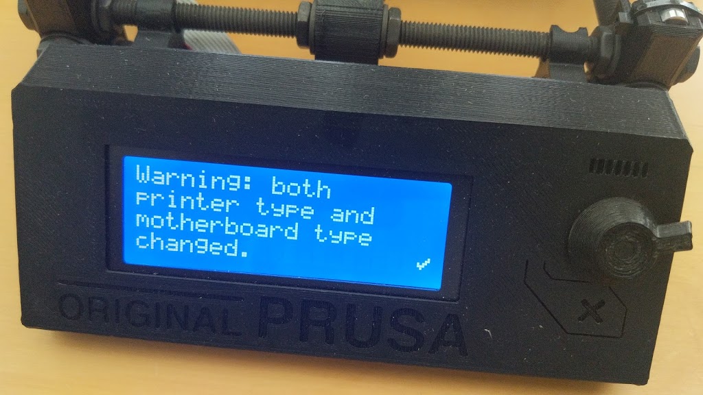
[14:19, 10/8/2019] Mik Lamming: Flashing the French version… ?
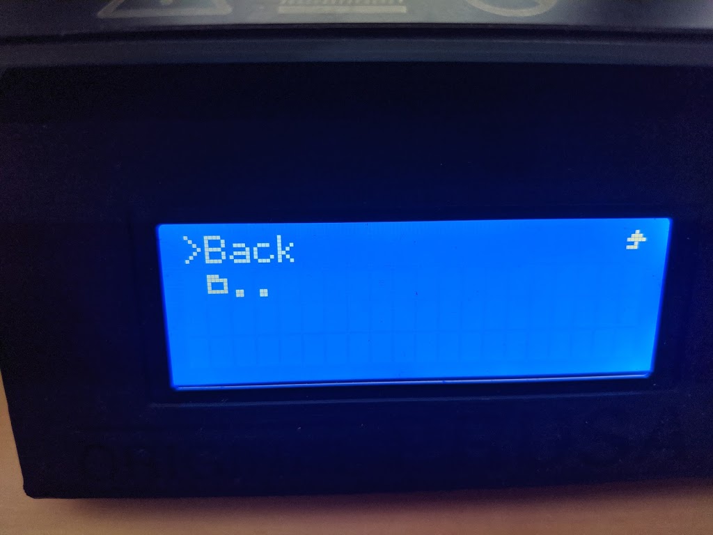
[14:29, 10/8/2019] Mik Lamming: I guess it flashed, but is this message OK?
[14:30, 10/8/2019] Mik Lamming: Now I’m going to try and print the treefrog example again. So two questions: Which of these is the right device to choose
[14:30, 10/8/2019] Mik Lamming: And do you hand-edit the gcode to turn down the fan speed, or is there some control somewhere?
[14:33, 10/8/2019] David Carkeek: If you’re in Slic3r there’s a setting.
[14:33, 10/8/2019] Mik Lamming: I am
[14:35, 10/8/2019] David Carkeek: I’m going to have to install the program to look at it because I can’t remember enough details to explain how to get there.
[14:36, 10/8/2019] David Carkeek: Did you install 2.2.8?
[14:36, 10/8/2019] Mik Lamming: No, no! I’ll figure it out. Just want to be sure I have the right controller specified. See aboce. There are lots of different 2.5S models
[14:37, 10/8/2019] Mik Lamming: 2.2.8 Slic3r
[14:37, 10/8/2019] David Carkeek: You have the right one selected.
[14:38, 10/8/2019] David Carkeek: All those other ones are if you have the multi-material unit installed.
[14:38, 10/8/2019] Mik Lamming: Ohhhhh! Duh. OK.
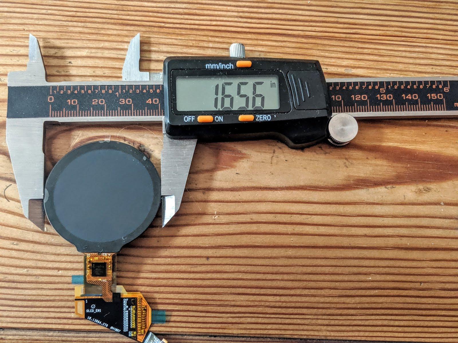
[14:42, 10/8/2019] Mik Lamming: Oh – what size noxel is fitted?
[14:43, 10/8/2019] Mik Lamming: nozzle
[14:51, 10/8/2019] Mik Lamming: This look right
[14:57, 10/8/2019] David Carkeek: It’s the standard nozzle. Maybe 0.25?
[14:57, 10/8/2019] Mik Lamming: OK thanks.
[15:00, 10/8/2019] David Carkeek: Maybe 0.4?
[15:00, 10/8/2019] David Carkeek: Probably 0.4mm
[15:01, 10/8/2019] Mik Lamming: I wonder if the hole looks like 0.4mm
[15:01, 10/8/2019] David Carkeek: Yes, it’s 0.4
[15:02, 10/8/2019] David Carkeek: I’m sure it would if it was clean.
[15:02, 10/8/2019] Mik Lamming: Oh thanks. That’s great. Did you try smaller nozzles at all?
[15:02, 10/8/2019] David Carkeek: Only the standard 0.4mm
[15:03, 10/8/2019] David Carkeek: It would be good to try others, probably.
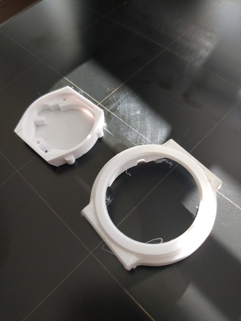
[15:03, 10/8/2019] Mik Lamming: The watch case looked pretty good at 0.4
[15:39, 10/8/2019] Mik Lamming: I set the min and max fan speed to 70%

Flash it right!

avrdude-slic3r -v -p atmega2560 -c wiring -P COM16 -b 115200 -D -U flash:w:0:C:UserslammingDesktopPRUSAprusa3d_fw_MK25S_3_8_0_2684_RAMBo13a_en-fr.hex:i

avrdude-slic3r: Version 6.3-20160220-prusa3d, compiled on Sep 16 2019 at 11:15:49
                Copyright (c) 2000-2005 Brian Dean, http://www.bdmicro.com/
                Copyright (c) 2007-2014 Joerg Wunsch


                Using Port                    : COM16
                Using Programmer              : wiring
                Overriding Baud Rate          : 115200
                AVR Part                      : ATmega2560
                Chip Erase delay              : 9000 us
                PAGEL                         : PD7
                BS2                           : PA0
                RESET disposition             : dedicated
                RETRY pulse                   : SCK
                serial program mode           : yes
                parallel program mode         : yes
                Timeout                       : 200
                StabDelay                     : 100
                CmdexeDelay                   : 25
                SyncLoops                     : 32
                ByteDelay                     : 0
                PollIndex                     : 3
                PollValue                     : 0x53
                Memory Detail                 :

                                         Block Poll               Page                       Polled
                  Memory Type Mode Delay Size  Indx Paged  Size   Size #Pages MinW  MaxW   ReadBack
                  ———– —- —– —– —- —— —— —- —— —– —– ———
                  eeprom        65    10     8    0 no       4096    8      0  9000  9000 0x00 0x00
                  flash         65    10   256    0 yes    262144  256   1024  4500  4500 0x00 0x00
                  lfuse          0     0     0    0 no          1    0      0  9000  9000 0x00 0x00
                  hfuse          0     0     0    0 no          1    0      0  9000  9000 0x00 0x00
                  efuse          0     0     0    0 no          1    0      0  9000  9000 0x00 0x00
                  lock           0     0     0    0 no          1    0      0  9000  9000 0x00 0x00
                  calibration    0     0     0    0 no          1    0      0     0     0 0x00 0x00
                  signature      0     0     0    0 no          3    0      0     0     0 0x00 0x00

                Programmer Type : Wiring
                Description     : Wiring
                Programmer Model: AVRISP
                Hardware Version: 15
                Firmware Version Master : 2.10
                Vtarget         : 0.0 V
                SCK period      : 0.1 us

avrdude-slic3r: AVR device initialized and ready to accept instructions

Reading | ################################################## | 100% 0.01s

avrdude-slic3r: Device signature = 0x1e9801 (probably m2560)
avrdude-slic3r: safemode: hfuse reads as D0
avrdude-slic3r: safemode: efuse reads as FD
avrdude-slic3r: reading input file “C:UserslammingDesktopPRUSAprusa3d_fw_MK25S_3_8_0_2684_RAMBo13a_en-fr.hex”
avrdude-slic3r: writing flash (218614 bytes):
avrdude-slic3r: stk500v2_command(): command failed

Writing | ################################################## | 100% 41.06s

avrdude-slic3r: 218614 bytes of flash written
avrdude-slic3r: verifying flash memory against C:UserslammingDesktopPRUSAprusa3d_fw_MK25S_3_8_0_2684_RAMBo13a_en-fr.hex:
avrdude-slic3r: load data flash data from input file C:UserslammingDesktopPRUSAprusa3d_fw_MK25S_3_8_0_2684_RAMBo13a_en-fr.hex:
avrdude-slic3r: input file C:UserslammingDesktopPRUSAprusa3d_fw_MK25S_3_8_0_2684_RAMBo13a_en-fr.hex contains 218614 bytes
avrdude-slic3r: reading on-chip flash data:

Reading | ################################################## | 100% 27.98s

avrdude-slic3r: verifying …
avrdude-slic3r: 218614 bytes of flash verified

avrdude-slic3r: safemode: hfuse reads as D0
avrdude-slic3r: safemode: efuse reads as FD
avrdude-slic3r: safemode: Fuses OK (E:FD, H:D0, L:FF)

avrdude-slic3r done.  Thank you.

Some success

I wonder what this means?
Need to adjust fan speed to prevent thermal runaway.


——————


Day 1

Just returned from UK, I went to have lunch with David.  To my surprise he carried two large boxes to my car and put them in.  He was lending me his ‘spare’ Prusa.  I’m not often left speechless, but…

Day 4

I managed to finish all the jobs I had in progress, and started to set up the Prusa.  Finding space for it was a challenge.
Took a while to figure out the UI.  I found a couple of files on the SD card that were something I had asked David to try out for me.  I tied to print them, and hey…  it worked and it did a great job.

Brenda is here so progress is slow, because we are gardening, and hosting fam.  More fam. tomorrow too.

For some reason I am obsessed with the idea of making a watch – well a series of them actually.  I think it would be cool to bang out a new variation every month.  I have been frustrated with all the watches I have seen, because, broadly speaking, none seem to do things I care about, or even do the things they are supposed to do smoothly – even telling the time isn't easy with a bunch of them.  But since telling the time is not a priority for me…  So why a circular display they ask…  dunno yet, except I think it's important to have a design that doesn't look like support-for-sickies.  
Making a watch is super-hard.  I assume that the reason that current watches are kind of lame is because it's just too hard to make them.  It's clear that the power and packaging issues are a major constraint, but I'm guessing that there are a lot of other things that I just don't understand – like charging. But there doesn't seem to be an experimental platform (like an Arduino) that is in a watch format that I can play around with.  Adding a new component is incredibly disruptive.   I'm also assuming that if someone had a design that was super-cool and useful, that skilled folks would bang it out in a few days.  But a watch needs such integrated design skills that it's hard for any single person to get their head around the major challenges at every level. So good ideas tend to happen at the hardware, or package, or software levels and interfere with each other so much that more disruptive ideas are slow to happen.
It would be great if I could make a watch that was almost as easy as software (!) to change as ideas evolved.  I'd sacrifice looks, and robustness for speed to iterate, and easyness of measuring usage parameters.  I just need my own team of 20 people – or is it 200?
So I stumble on trying to understand the issues.  In the absence of a team, and megabucks, but in the presence of obsession, I try to keep my aspirations in bounds.
Clearly I can't make a watch in one go.  I need to figure out how to: 1) talk to various components; 2) power all the different power domains; 3) measure where all the power goes, and lastly; 4) how to conveniently recharge it.  So a watch simulator board is first step.  I'll use an nRF52 connected to a board with options for different crap to be attached.  Kind of like TS05b but probably a lot more clunky that your neat design, because of the display.  I suppose there will be a few iterations of that.  Then the next phase is to transform it into a wearable, and add an IMU and whatever else can be squeezed in.
Now back to Earth.  I have made a footprint for the teensy touch-panel connector.  I'm not sure I have all the dimensions, right, but it's a start I guess.  I found a display connector online, so all I have to do is plonk them on a board and connect them.   I have found this to be a lot harder than I thought because the display demands the connectors to be on opposite sides of the board.  I assume that's going to make it almost impossible to solder – notwithstanding the fact that the connector pitch is absurdly tiny.
I theory, the board layout is trivial now because I'm just connecting the SMD connectors to standard headers and thence by patch wires to a Nordic eval boardI really do understand so much more of the tour-de-force you exhibited to build those TS boards – and you banged out a whole bunch of them.

If I can connect the display and make software work, then I'll work on the PSU side of things.  
Whatever you are able/allowed to do to help is gratefully received of course, but I'm very sensitive to you conflicts of interest.  I'm sure my feeble efforts must be pretty laughable compared with the stuff going on at Am., but it gives me pleasure to learn all this new stuff.


On Mon, Jul 8, 2019, 07:29 David Carkeek <dcarkeek@gmail.com> wrote:
Didn't I already respond? It looks like I didn't. I'm almost certain that you will not find a parts library that has the connector footprint you need. Since you indicated that you were going to make one yourself, how is it coming along? When I was trying to make footprints I was frustrated by the inconsistent way that dimensions were given. MuRata datasheets were the worst. 

Are we going to make a board?

On Tue, Jul 2, 2019 at 5:52 AM Mik Lamming <mik@lamming.com> wrote:
Oh I'm using Eagle as usual.  I kind of understand it.  It isn't really a layout problem, it's that I can't find a parts library for the connectors.
I'm trying to make a trivial board to connect all the different displays I have collected to a set of header pins, so I can figure out the driver issues.  Modern displays use MIPI which requires fast hardware in the uC to drive it.  I will have to use SPI which is slow.  Nordic doesn't have MIPI, but ST does.  I thought about using an ST, but that makes everything else so much more complicated, and I'm already out of my depth.  
My challenge is that the displays I have been able to get generally have tiny connectors.  
Worse, my most practical display uses a connector that seems to be obsolete.  Of course – that's why I could get it!  I have a few connectors, but I just can't seem to get the Eagle parts library, so I am making my own.  Measuring stuff is hard of course.   Then the challenge is going to be soldering something that has 10 pins and is 4mm long.  I expect it will take me a few iterations, but I'm enjoying learning the process.

On Tue, Jul 2, 2019 at 6:17 AM David Carkeek <dcarkeek@gmail.com> wrote:
What program are you going to be using? At one point I could have done it in Eagle but I have forgotten almost everything. Since I was able to do it it wasn't that hard to figure out, so I can probably do it again. Also, Yali would be overjoyed to have something to do for Touchstone.

What do you think about making a platform board with all of the circuits you are interested in characterizing?

On Mon, Jul 1, 2019 at 4:01 AM Mik Lamming <mik@lamming.com> wrote:
Is there an obvious place to go for component outlines.  I need to make a breakout board with the connector on it, and I can't find it.  I can make it I guess, which would be a new skill, but I'm not sure I'd trust it.
Oh I’m using Eagle as usual.  I kind of understand it.  It isn’t really a layout problem, it’s that I can’t find a parts library for the connectors.
I’m trying to make a trivial board to connect all the different displays I have collected to a set of header pins, so I can figure out the driver issues.  Modern displays use MIPI which requires fast hardware in the uC to drive it.  I will have to use SPI which is slow.  Nordic doesn’t have MIPI, but ST does.  I thought about using an ST, but that makes everything else so much more complicated, and I’m already out of my depth.  
My challenge is that the displays I have been able to get generally have tiny connectors.  
Worse, my most practical display uses a connector that seems to be obsolete.  Of course – that’s why I could get it!  I have a few connectors, but I just can’t seem to get the Eagle parts library, so I am making my own.  Measuring stuff is hard of course.   Then the challenge is going to be soldering something that has 10 pins and is 4mm long.  I expect it will take me a few iterations, but I’m enjoying learning the process.

On Tue, Jul 2, 2019 at 6:17 AM David Carkeek <dcarkeek@gmail.com> wrote:
What program are you going to be using? At one point I could have done it in Eagle but I have forgotten almost everything. Since I was able to do it it wasn’t that hard to figure out, so I can probably do it again. Also, Yali would be overjoyed to have something to do for Touchstone.

What do you think about making a platform board with all of the circuits you are interested in characterizing?

On Mon, Jul 1, 2019 at 4:01 AM Mik Lamming <mik@lamming.com> wrote:
Is there an obvious place to go for component outlines.  I need to make a breakout board with the connector on it, and I can’t find it.  I can make it I guess, which would be a new skill, but I’m not sure I’d trust it.
 
I have managed to buy one of the AMOLED displays with a touch screen.  It looks like a real bugger to interface, but I guess the challenge will do me good.
I have got a belly-full of documentation, some of which I don't understand.
I think there are displays that are easier to interface, but they are slower, dimmer, and don't have a touch screen.  
I see three main challenges:
1) building some kind of interface board with appropriate power-supply for both AMOLED and touch screen – this is daunting
2) figuring out driver code
3) exploring ways to save power – perhaps flogging a dead horse.