I just realized that I didn’t fully understand a feature of the DW hardware. Although they talk about responding after a fixed delay, they don’t exactly do that.
The ranging process involves sending a packet on a round trip to a peer, which holds the packet for a fixed, and known period before sending it back to the sender.
The hardware will transmit the packet when a system counter reaches a specified value Ttx The counter is 40 bits long, and wraps every 17 seconds, so it increments a bit every ~16 picoseconds. The same kind of system counter is used to notice the arrival time, Trx, of the packet demanding the response. So you would think that Ttx =Trx + fixedDelay.
In fact they use Ttx = (Trx + fixedDelay) & 0xFFFFFFFE00 which potentially lops about 8ns off the arrival time. i.e. 2+ meters! Why do they do this, and why doesn’t it matter?
Here’s my theory. The actual time we want the packet to leave the antenna is going to be a little after the radio streams out the signals, because they have to crawl down to the antenna. So there is an antenna delay. So the radio needs to send the bits out a little early so they leave the antenna at the desired instant.
Now perhaps the chip can’t do carry-arithmetic, so they just make it easy to OR in the antenna delay. In any case the don’t bother unduly about getting the transmit time correct. All they need to ensure is that they have delayed long enough for the receiver to wake up and start listening.
Ttx = antennaDelayTime + (Trx + fixedDelay) & 0xFFFFFFFE00
Now I’m not sure if the actual transmit time stamp is simply computed and taken as fact, or if some analog magic causes the system counter to get copied at the critical moment. I suspect the former.
Adding in the antenna delay could produce a value that’s larger than 40 bits. But the system counter wraps at 40 bits, so the start time is masked at 40 bits too.
Ttx = (antennaDelayTime + (Trx + fixedDelay) & 0xFFFFFFFE00) & 0xFFFFFFFFFF
A potential snag with this mechanism is that something could slow up the host microprocessor from calculating the transmit time. If that takes so long that the transmit time passes then the game is over, and everything has to start over.
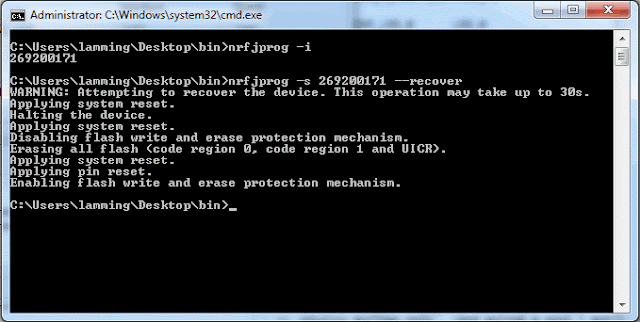
In order to run a .hex file you don’t need to install Eclipse or any of that crap. You just need to install the “flasher”, erase the memory, and then flash the test program.
Flashing test program #1
- Go to the TESTING directory
- If you don’t have it installed already, download and install JFlashLite_V485a.zip
- Download the test program Blinky32k_C_nRF51822.hex
- The UI to JFlashLite is tedious but easy.
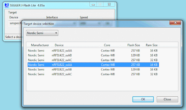
- Make sure to specify the correct processor using the pull-down menu. nRF51822_xxAA
- Erase the memory first time around.
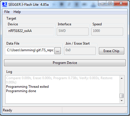
- Set the “Data file” field to point at the test program .hex file
- Press “Program Device”
- After the flashing process, the program might not start automatically (probably because there is a fossil breakpoint at “main”). If it doesn’t start, then power-cycle the board.
while (true)
{
LED_clearAll();
nrf_delay_ms(500);
LED_setAll();
nrf_delay_ms(500);
LED_clearAll();
for (int i = 0; i < LEDS_NUMBER; i++)
{
LEDS_INVERT(1 << leds[i]);
nrf_delay_ms(500);
}
}
Test program #2
- Plug the USB port into the PC – a new COM port should be created
- Open your favorite terminal-emulator (e.g. Putty?)
- Set 38400, 8, 1, parity:none, flow-control:none
- Download and flash the test program Blinky32K_USB_C_nRF51822.hex
while (true)
{
LED_clearAll();
nrf_delay_ms(500);
LED_setAll();
nrf_delay_ms(500);
LED_clearAll();
for (int i = 0; i < LEDS_NUMBER; i++)
{
LEDS_INVERT(1 << leds[i]);
nrf_delay_ms(500);
}
ts_uart_init();
TS_TRACE(“rn———–rn%s HW:%s SM:%s SW:%s(%s %s)rn”,
MANUFACTURER_NAME, DEVICE_NAME, SDNAME, SERVICE_NAME, __DATE__,
__TIME__);
}
JFlash Log
Troubleshooting
Went to bed exhausted last night. I’m really having a lot of trouble getting the ranging to work. So far I can send and receive packets. I think I can send packets after a fixed delay, but I can’t seem to receive them correctly.
Some of my problems are clearly just not understanding how to configure the chip for the subset of stuff I need to do. Then there are illogical behaviors, and frankly — chip bugs.
Status bits are set in the wrong chronological order.
This sequence of trace messages shows the problem. I’m joining battle here at the point when one TS has sent a “ranging init” packet to the other. A ranging-init packet is the “serve” in the ping-pong game of packet exchanges between the two peers). After sending that packet the radio goes to sleep, an I’d expect to get notification of the packet having been finally sent, but in fact I get told (very reasonably) that the radio has woken up: (SYS_STATUS_SLP2INIT); that the clock has locked up OK: ( SYS_STATUS_CPLOCK); that a packet preamble has been successfuly decoded (SYS_STATUS_RXPRD ); that the clock has lost lock again (SYS_STATUS_CLKPLL_LL ); and that the rest of the packet timed out (SYS_STATUS_RXSFDTO). All of this gets reported at a higher level in the DW IRQ handler as a “receive error” (DWT_SIG_RX_ERROR)
After all that is said and done I get to hear that my original transmission has completed (DWT_SIG_TX_DONE). This bizarre sequence makes it difficult to build a rational state-machine, and indeed my code (and I actually) get’s confused and hangs up.
(25931) ranger_rxcallback DWT_SIG_RX_ERROR
SYS_STATUS_IRQS SYS_STATUS_CPLOCK SYS_STATUS_RXPRD SYS_STATUS_SLP2INIT SYS_STATUS_CLKPLL_LL SYS_STATUS_RXSFDTO
LISTENING_FOR_RANGE_INIT_RESPONSE
(25932) ranger_txcallback DWT_SIG_TX_DONE
It isn’t even possible to reply to every ranging-init packet
WAIT_TX_RESP_DONE
(2839) listener_rxcallback DWT_SIG_RX_ERROR
SYS_STATUS_IRQS SYS_STATUS_CPLOCK SYS_STATUS_RXPRD SYS_STATUS_SLP2INIT SYS_STATUS_CLKPLL_LL SYS_STATUS_RXSFDTO
LISTENING_FOR_RANGE_INIT_RQ
(2840) listener_rxcallback DWT_SIG_RX_ERROR
SYS_STATUS_IRQS SYS_STATUS_CPLOCK SYS_STATUS_RXPRD SYS_STATUS_SLP2INIT SYS_STATUS_CLKPLL_LL SYS_STATUS_RXSFDTO
LISTENING_FOR_RANGE_INIT_RQ
too late
Chip is buggy
- calculate the area under the graph – the actual units are not important, because we care about differences
- traces could be superimposed to spot subtle differences and problems.
Scope is scheduled to arrive on Friday by UPS. Since it's going to my PO Box I might not be able to get it until Monday. I could probably ask for it to held at the UPS depot in Sunnyvale if I really need it next weekend.A Picoscope would be perfect for you. Even the base model decodes SPI and I2C, and the 10 MHz model ($149 with two probes) has plenty of bandwidth for looking at SPI/I2C/JTAG.———- Forwarded message ———-
From: <orderstatus@tequipment.net>
Date: Sat, Jul 11, 2015 at 9:54 AM
Subject: Your TEquipment.NET Order Has Shipped! – Order# A075652
To: dcarkeek@gmail.com
Cc: dcarkeek@gmail.com
![TEquipment.NET]()
Order #A075652
07/10/2015
Cust# 052380C
Thank you for shopping at TEquipment.NET!
Your package shipped on 07/10/2015, and a tracking number has been generated.
In order to reduce handling and improve our shipping time, we now transport many of our packages directly to regional UPS/FedEx hubs. This may result in a short delay in finding your tracking number on their website. Rest assure that your package is on its way.Please see below for your order information and tracking number.
SHIPPING SUMMARY:
Myself Ship To: DAVID CARKEEK
1750 LUNDY AVE #612871
SAN JOSE, CA 95161-7116
US
4084723787
Shipping Method: Ground
Item/Description Qty Carrier Tracking# Primary Warehouse: ![RIGOLDS1054Z]()
RIGOLDS1054Z 50 MHz Digital Oscilloscope with 4 channels plus 12 Mpt memory, 1 GS/s sampling rate.
1 UPS 1Z6619070373403218 To log in to see your complete order status, including any items not on this shipment, please visit: https://www.tequipment.net/service/order/
Thank you again for shopping at TEquipment.NET. We appreciate your business and look forward to serving you in the near future.
Your Customer Service Team,
We are here to help you.
TEquipment.NET
205 Westwood Ave
Long Branch, NJ 07740
1-877-571-7901 – Toll Free
732-222-7077 – Local Tel
732-222-7088 – Fax
I’m of the opinion that the person who wrote this code wasn’t very experienced because it’s messy and poorly structured.
I was thinking of a couple of things:
- There is a long-term data storage challenge, but saving stuff to a uSD card is thristy work. To make sure nothing get's lost you have to write often. Writing partial-pages is bad because the whole page has to be erased (v. expensive as I understand it) and re-written. So you get to save power at the risk of losing data occasionally. The alternative is to have a non-volatile FRAM cache.
- The other challenge is on-board signal processing, and pattern recognition. The technique is to build a tree-structured pipeline of filters that makes a single pass over the data. The windows can get large and the intermediate results are cached to avoid unnecessary read/writing. Obviously there isn't enough RAM to do much of that, but 500kB could make a difference.
It's very interesting. Wouldn't it be only 500kB though? The density has to improve a lot before we could consider it for data storage.On Thu, Jul 9, 2015 at 9:06 AM, Mik Lamming <mik@lamming.com> wrote:


