These instructions assume nothing is plugged in or running, so we are both on the same page.
Perf board TS06.2:
  1. Connect: Power, UART and Jlink. 
  2. Prepare Putty.
  3. Setup jflash-lite: Device is nRF51822_xxAA
  4. Erase mem. 
  5. Don’t load any soft-machine
  6. Flash with “Reflector-1w_(6b)_UART_TS06_2.hex”
  7. Power-cycle.
  8. No LEDs flash, after startup sequence
  9. You should see this:

TS06.3

  1. Connect: USB and Jlink.  Prepare Putty
  2. NB! This device is nRF51822_xxAC
  3. Erase mem
  4. Load soft-machine “s130_nrf51_1.0.0_softdevice.hex”
  5. Load my software “Initator_1w_UART_TS06_3.hex”
  6. Push the reset button – nearest the uSD card
  7. Should see exactly this sequence: see this video

MCP

  1. Plug in the little BLE dongle.  Note the serial# on the chip!
  2. Connect MCP to the dongle.  Make sure you specify the correct serial# or you may connect to the JLink instead, and since it may ask to reflash the dongle, this could be bad.  If it does ask to feflash dongle select the “slow” option.
  3. Start discovery.  This can take several attempts at 5 seconds each.

  4. Notice above, that a foreign BLE device (0x68644B269739… my neighbor’s) has been discovered!
  5. Select “ts” from the list, and click “Select Device”.  Wait up to 5 seconds… If it connects you should see this LED pattern:

    Weasle words: BLE is a bit unpredictable at this point. It should connect, and you should see a list of characteristics.
    If not press “Connect”, or start over.
    If no services characteristics are printed then press “Discover services”

  6. Click “Enable Services”

Running a range operation

  1. Click last item in list, type in 2-digit hex#, and press “Write”.

  2. If it works you should see something like this on the putty channel, and the MCP characteristic above the one you typed in will show the range in hex-centimeters with the bytes reverse.  Great huh  EF-FF => FFEF => -17cm
    ?
    .
N.B. I have bum antenna delays set up on mine, so the ranges are whacky.

I made an automatic antenna delay calibration program.  It hill-climbs to find the antenna delay that produces the result that is closest to the truth.

Each time it changes the antenna delay it transmits the new value to the peer, which sets up it’s own antenna delay to match.

It produced an odd result.  The vertical axis is antenna delay, and the horizontal is meters.  I was trying to home in on 1.67 meters.   There seem to be two sweet areas.   Why is this?

I think I see a serious problem with low-power operations.  The crystal used by the DW module takes quite a long time to warm up, and settle down.  Below are two diagrams.  Labelled “Figure 2” on the left is DW’s version.  On  the right is a diagram copied from a comprehensive discussions of crystals from HP,

Notice that DW’s version has been edited to remove the important units.
HP’s caption:
Figure 25. A is a RTXO warm up curve. B, C and D are typical TCXO warm up characteristics. The long time (3 hours) is due to changes in temperature inside the instrument. E and F are oven oscillators. Stability is achieved in ≈20 minutes.
That might be a problem as far as instant startup is concerned unless we keep the DW crystal running.

David writes…

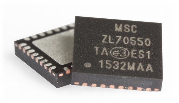
Microsemi has a new radio, Zl70550, that’s clearly better than the one we were looking at. the receive current is a little higher but the sensitivity is much better. The sleep current is only 10 nA vs 500nA. The maximum transmit output power is higher at lower power consumed (more efficient) only 5.3mA at 0 dBm. Compare with the nRF51822 that consumes 10.5 mA @ 0dBm. It has 40 dBm of RSSI range with 2dB of RSSI resolution.

With a typical current consumption below 2.75 mA in transmit (–10 dBm) and below 2.4 mA in receive (–95 dBm sensitivity), and a data rate of 200 kbit/s, the ZL70550 device enables bidirectional RF links over a distance of more than 100 meters (based on antenna gain and operating environment). A sensitivity of –106 dBm can be achieved by optionally increasing the receiver current consumption (to approximately 3.2 mA), enabling FEC, and using the lowest data rate.

Inline image 1
Looks interesting:

The device includes the Z-Star protocol, which is a powerful and highly optimized MAC that performs complete packet transmissions with acknowledgments and automatic retransmissions on failed receptions. This built-in protocol eliminates the need for processor intervention in packet processing, allowing the processor to go to a power-save state or to perform other critical application processing. Additionally, the MAC supports other user modes of operation with selectable options like CRC, FEC, and auto length.

CSP package available that’s just 2mm x 3mm. QFN package available 5mm x 5mm.
I tried calling Microsemi sales but just got VM.
Carmen Isham

Features

  • Ultralow current of 2.4 mA in receive and 2.75 mA in transmit
  • Ultralow sleep current of 10 nA
  • Maximum TX output power of 0 dBm
  • Maximum RX sensitivity of −106 dBm
  • Wide supply range of 1.71 V to 3.6 V
  • Operates between 779 MHz and 965 MHz (915-MHz ISM band in North America; 868-MHz SRD band in Europe; 779-MHz to 787-MHz band in China; 916-MHz to 930-MHz and 950-MHz to 956-MHz bands in Japan)
  • Raw data rates of 200 kbit/s, 100 kbit/s, or 50 kbit/s
  • Very small footprint
    • Few external components (crystal, resistor, and two decoupling capacitors)ZL70550 QFN photo magnified
    • Available in 29-pin CSP package (2 mm by 3 mm) or in 32-pin QFN package (5 mm by 5 mm)
  • SPI bus slave for packet data and register access
  • Built-in MAC
    • Support for Microsemi Z-Star or user protocols
    • Transmit and receive buffer
    • Optional automatic CSMA packet transfers
    • Efficient header optimized for small or large payloads
    • Optional preamble, frame sync, length, FEC, and CRC
  • Industrial temperature range (−40°C to 85°C)
Notice the “No charging required”. 1.5 year estimated battery life.

http://www.timex.com/watches/metropolitan-tw2p81700

Track Your Active Life.
This stylish activity tracker blends the functionality of an activity tracking band with the look and feel of a traditional analog watch. The unique fourth hand tracks daily steps, distance and percent to goal right on the dial. The Metropolitan+ uses Bluetooth technology to connect to the Timex App on your phone that tracks daily activity, including steps, distance and calories burned. The phone app stores your data so you can access and analyze it at any time. This watch also features quick release straps so you can easily change your look in seconds.
  • Track steps, distance and calories burned
  • Sleep Metrics (coming Spring, 2016)
  • Sync with your phone
  • No charging required
  • Water resistant
  • Indiglo® Night-Light

– See more at: http://www.timex.com/watches/metropolitan-tw2p81700#sthash.5VQuJhsl.dpuf

Inline image 1
Inline image 2
From instruction sheet: 
FEATURES
• Classic Analog design
• BLE connection with Smartphone application (iOS and Android formats)
• Activity tracking displayed on watch dial in both steps and distance.
• Percent of goal achievement displays on the watch dial in both steps and
distance
• Smartphone application displays actual count and percent of set goal
achieved for Steps, Distance and Calories
• Smartphone application retains activity data and displays activity by day,
week, month or year.
• INDIGLO® night-light
• Estimated battery life of 1.5 years

————————–
Ah, it is just a mechanical UI display for the app on your phone.  I bet you have to turn the BLE on/off manually.

A momentus day!   It’s actually 2.2 meters on the tape measure.
The first time it actually worked… and then it died.
There are two BLE peers.  We are looking at the advertising side of the transaction.  The advertiser offers a ranging service.  

Protocol

  1. The client-side notices the advertisement and connects to the advertiser.  
  2. If the connection succeeds, the client fires up its DW in listening mode,
  3. Then it uses BLE to ask the ranging service to range it.
  4. The advertiser fires up it’s own DW and performs a ranging cycle.
  5. It then shuts down it’s ranger.
  6. Then it updates the “range” property of the connection, which notifies the client
  7. The client now has the range

Attempt #2

After some cleaning up, and further work, it started to work.   This is only doing single-sided ranging, i.e. 1 round trip.
In the following example:
  • White   is main controller thread activity (the app)
  • Cyan is BLE activity
  • Green   is DW activity

I wondered if we had a hardware issue, or a software issue, or both.
I just tried to copy your measurement process with the Nordic eval board.  Here’s what I did, and I’m not sure of my workings, so check me out.
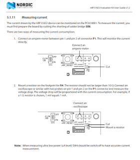
Notice the last note.  Maybe that’s significant for us?
  • I looked through hundreds of loose resistors and found one that claims to be 10 ohms.
  • Then I kind kludged it across the current measurement pins of the PCA10001, using my meter probes, like this.
  • Then I ran my software and put the Nordic to sleep (allegedly)
  • My meter looks like this
  • Then I found an ohms-law calculator and plugged in some values.
Well doh!  1.2mA

I have to measure the voltage which is…. 

2.367Volts
Watts = Volts * Amps, so the answer is 2.367 * 0.0012 = 0.0028404  or 3mW.  This is a lot more than the µW I was hoping to see.   So it looks like there’s a lot of stuff still switched on.

Learned something significant

I read up some more on power saving.  Having the debugger running has a huge effect.  Here is my experiment that proves the point.
I made a simple program that:
  1. turns on a LED
  2. waits for a button press
  3. shuts down.

When running in debug mode the voltage measured across the bridge is 12mV

If I disconnect the debugger, the shutdown voltage is 0.1mV = 0.0001V.  So the current is 0.00001A.
So the wattage is

2.367 * 0.00001 = 0.00002367 W = 24µW.   


That’s a lot better, but it’s still 30x what I should be seeing.


Ahhh!   And then it struck me.  The meter has pooped out.  What I need to do is use a bigger resistor in the bridge.  I wonder what that will do?
The voltage now seems to be down to 2.426V, and the sleep current now measures 0.2mV across a 100Ω bridge, so the current is 0.002mA = 2µA ??

So the math is now 2.426V * 0.000002A = 0.000004852W 5µW.

David: For sale by Google:

https://store.google.com/product/huawei_watch


———–
It’s nice looking, and has a circular display.  1.5 day battery life!

Comments:

Button fell off after 3 months of very light use, company says no repairs can be done and warranty is voided since the button fell off WTF  (Trump Tech)

​Looks like they have problems making a small vibe too.​ 

Very excited for sound for my Huawei watch. The vibrations are really weak so I miss a lot of notifications (I know, sort of defeats the purpose of a ‘smart’ watch) so a sound backup would be great. Now if they can only improve the notification vibration intensity!

​   ​
​Jeez the world is rushing ahead isn’t it.​

This is a really good explanation from David.
Here’s the trace after Scan2560m12msNoLeds.hex boots between the 12ms pulses.
Inline image 1

The meter measures 85.8mV. The scope measures 88 mV.  MGL: So it’s good that they agree

There’s 2.8072V on one side of the 10 ohm resistor and 2.7215V of the other side of the resistor, or 0.0857V. This matches with the 85.8mV measured across it. The Nordic is seeing 2.7215V.  This is where the 2.72 comes from that he uses later.
I measured the 10-ohm resistor and it was very close to 10 ohms but contact resistance (no substitute for David’s experience) is a problem, so I assume that the resistor is 10.00000000… ohms. It’s not, but close enough.
Current: I=V/R=0.088/10=8.8mA constant.
Power: 2.7215*0.0088=23.95mW
So the program is soaking up a constant 8.8mA from something.  That’s clearly a showstopper.  On my Fluke, I see a constant 13.51mA when the program is paused.  When the DW turns on, and is just waiting for a command from the Nordic, the current goes up to 21.51 – exactly 8mA!
Here’s the 12ms pulse.
Inline image 2
The solid cursor is “A” and the dotted cursor is “B”. The pulse measured in the center of the rise and fall times is 11.8ms. The height is 127mV. The increase in current is 0.127/10 = 12.7mA. The power of the pulse is V*I=2.7215*0.0127=0.03456 watts. The energy of the pulse is 0.03456W * 0.0118S = 0.4078 mW-S=1.1329e-7 W-H.  
There is that little pulse at the beginning of the longer pulse. I don’t know how to calculate it. For now let’s ignore it.  That’s probably some soft-machine processor activity setting up the radio for the next listen event.
Inline image 1
More troubling then the pulse is the 8.8mA the Nordic is drawing constantly. What is turned on (or what has been turned off might be a better way to look at it).
It could easily be the case that there are parts of the Nordic that are not turned off.   I need to systematically go through the init. process and see what’s still turned on.  How can we track down stray currents so I can know where to focus my attention?
—————————————–
MGL: I assume that you are just measuring the Nordic current, and nothing else?

The solid cursor is “A” and the dotted cursor is “B”. The pulse measured in the center of the rise and fall times is 11.8ms. The height is 127mV. The increase in current is 0.127/10 = 12.7mA. 

​​

The power of the pulse is V*I=2.7215*0.0127=0.03456 watts. The energy of the pulse is 0.03456W * 0.0118S = 0.4078 mW-S=1.1329e-7 W-H.  

So I want to make sure I understand your results.
  • 11.8 ms pulse seems close enough to 12 for government work. Good,
  • The increase in current is 0.127/10 = 12.7mA.   — divide by 10 because of the 10Ω resistor?
  • The advertising pulse draws 12.7 mA for 12ms
  • Watts = volts x amps so 

    power is 2.7215*0.0127=0.03456 watts = 35mW.

  • The energy of the pulse is watts x seconds = 0.03456W * 0.0118S = 0.4078 mW-S=1.1329e-7 W-H.
  • So to make it more tangible…a CR2032 is good for about 200mAh at 2.8V so that’s  0.56 Wh (assuming it is not abused)
  • So it ought to be able to scan 0.200  * 2.8 / 1.1329e-7 = 4943066.46659 times – assuming it was switched off the rest of the time.
  • If scan requests were issued every second, that’s 0.200  * 2.8 / 1.1329e-7 seconds in days = 57.2114174 days.  

USB is a convenient way to get power, but we might not need it any longer, at least for debugging IO.

The latest Segger software J-Link V5.10q has a terminal emulator (called RTT Viewer) that will talk to the TS06.2 over the j-link.  The good news is that it seems really fast – faster than the 38K4 that I’m using over USB.

The nice thing about it is that attaches to the Jlink debugger automatically.  Most of the time it sits there showing an annoying little progress window.

After the program has loaded into the TS06, the JLink viewer pops open and displays IO.  Here’s my dumb test program.

This means that we could dump a bunch of driver code and save some space, and get rid of a chip off the board… or not.