This table (FullSpec p21) is interesting, and looks like it contains enough info to answer preliminary power questions (if I knew how to do calcs)
They appear to nicely give a wet-finger estimate for a ranging operation
4uA with RTC on  SLEEPING
.5ms @ 10mA to  STANDBY
7-8 ms @ 18.5mA RANGING
So how many range operations can we do on our battery, neglecting other processing overhead?

//Mik

On Thu, Jan 22, 2015 at 9:32 AM, Mik Lamming <mik@lamming.com> wrote:

Oh thanks.  Well done sirrah!

I hope to be through this wretched video crap soon, and back to TS – assuming I'm allowed.  I need to rent a cupboard-sized office at a secret location about 10 yards up the street!

//Mik

On Thu, Jan 22, 2015 at 9:11 AM, David Carkeek <dcarkeek@gmail.com> wrote:

I have copied most of the files to TS06BeSpoonForum files. They seem to be pretty good about updating stuff. The latest release is 1/15.

When I downloaded the big zip files Chrome said "This file is malicious". I dismissed the warning but perhaps it's best to be cautious in case Fabre Pascal's computer is infected with something (I doubt it).

On Wed, Jan 21, 2015 at 10:10 PM, Mik Lamming <mik@lamming.com> wrote:

No I didn't.  I'll track them down and have a look tomorrow.

//Mik

On Wed, Jan 21, 2015 at 12:14 PM, David Carkeek <dcarkeek@gmail.com> wrote:

Did you look at the files Franck alluded to? It's interesting to see how many people have viewed them. That's probably the number of entities that have ordered hardware.

I haven't downloaded anything yet.

This is not a general review of BLE!  I have collected the following facts in the context of trying to establish the practicality of our proposed WUR idea.

Some important facts about BLE Phy

Raw data rate is 1Mb/s

BLE uses Gaussian frequency key shifting (FSK)

BLE uses 40 channels from 2402MHz, 2404… 2480MHz
If 2402MHz was the center frequency (CF) then ‘0’ would be CF-180kHz, and ‘1’ would be CF+180kHz
Maximum xmit power is +10dBm (10mW)
Receiver sensitivity must be better than -70dBm
Path loss is 40+25log(meters)
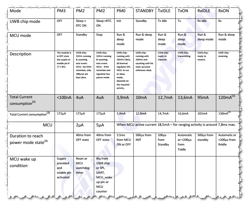
The longest packet possible lasts 376uS (Pmax)
Packets have a 37-byte payload and 10-bytes of decoration = 47B
Bytes are sent least-sig-bit first.

Whitening

FSK receivers are unable to receive very long sequences of bits of the same value because they assume that the center frequency of the transmitter has wandered off in the direction of the ‘0’ frequency.  To protect against this a whitener function is used. The whitener is a pseudo-random sequence of bits that both sides of the connection know (it’s kinda like encryption).  The whitener is XORed with the packet at sender and receiver.  So the packet payload will always look like it contains white noise.

Broadcasting Modes

Nodes broadcast for two reasons:  to say they are ready for a connection (advertising), to broadcast some data (like temperature).  They can do both at the same time.   Payload data has to conform to a protocol that enables anyone to understand it.  e.g. It’s a temperature.  The list of BLE-allowable data objects is large.
General advertising is for nodes that will accept a connection request from anyone.  Direct advertising is for nodes who are prepared to be connected to by specific peers.  They are required to advertise every 3.75 milliseconds. So a scanning device only has to listen for 3.75 ms.
Sending packets this fast clogs up the advertising channel, so it is only allowed to go on for a maximum of 1.28 seconds (341 packets).
So ordinary advertising is one way to generate a WUR signal to a node that’s asleep. The downside is that lots of devices may be trying to do this in their normal course of operations, so some level of packet analysis would be required to avoid waking up for all of them.

Connection modes

Master is the name given to the node initiating the connection.  The node that broadcast its preparedness to accept a connection will become the slave.   Counter intuitivity warning: Since the broadcaster started the ball rolling you would think it would be the master, but nay!  
After a connection is established there is a mandatory 1.25ms delay before the first data packet is sent to allow batteries to recover after a possibly exhausting advertising procedure.
When in connection, the master is required to send a packet at regular intervals on the same frequency or the slave considers the connection is terminated after N traffic-free periods.  N is called the slave latency (SL).  And there must be a 150us gap between packets.   
The interval between connection packets called the connection interval (CI), can be as short as 7.5ms to 4s.  (The internal clock has to be recalibrated every 4s!!)  The maximum time a slave is prepared to wait for a packet, called the supervision timeout (ST), is 32s.  
This seems complicated but the basic idea is that ST = CI*(SL+1) < 32s.   So with a CI or 100ms and SL=9 then ST = 1 sec.
Put another way, the slave has to wake up and listen for a connection packet every 32 seconds.  If CI = 100ms then SL has to be 319 or less.
FACTOID:  The slave has to wake up every 32s to maintain a connection.  It has to listen for a minimum of the CI interval = 7.5ms.  But then the master has to transmit a packet every 7.5ms! 
However BLE folks say giving the slave just one opportunity is a bad strategy (page 97).  They recommend six attempts.  So when CI=100ms & SL=9, the ST should be set to 6 seconds, rather than 1 second, giving the slave 6 opportunities, instead of just 1.  So in the example above the ST should be 6 times larger – i.e. 6s.    If the ST is 32, and you want 6 opportunities, then the CI is 32/6=5.3s which exceed the 4s max allowed.

A typical scenario for transmitting data on a button press is to have BLE connection with relatively low connection interval but with high slave latency. Low connection interval will enable your device to send packets frequently, i.e. to have a good response on a button press. High slave latency will allow your device to not send packets on every connection event, thereby saving current.

and this blog

Sleep Clock Accuracy

Having more accurate clocks would save power.  The clock accuracy is used to determine the uncertainty window of the slave device at a connection event, when the clocks are re-synchronized.
A crystal that is 20ppm at room temp, might be 50ppm at 0C or 85C.  The protocols have to assume the worst.
To be extreme, if master and slave have clocks that are 500ppm, then their total drift from one another could be 1000ppm.  In a second, they could have drifted 1 millisecond apart.   So the slave has to wake up 1 millisecond early, and stay on for an extra millisecond.
If the device is waking up at the maximum connection interval of 4s, then the extra “on” time could be 8ms.   
  • External crystal: Using an external 32.768 kHz crystal is the option that gives the lowest current consumption. If you have this on your board, you should use it. You have to choose the appropriate accuracy for your crystal, so that the softdevice can take the accuracy into consideration to know how much the clock may drift over a certain period. It will use this information to make sure it compensates correctly and wakes up the chip just when needed.
The Nordic code (nrh.sdm.h) contains these options for crystals.  Presumably we could add our own to the list. NB. The best is 20ppm.

enum NRF_CLOCK_LFCLKSRCS
{
  NRF_CLOCK_LFCLKSRC_SYNTH_250_PPM,                       /**< LFCLK Synthesized from HFCLK.                    */
  NRF_CLOCK_LFCLKSRC_XTAL_500_PPM,                        /**< LFCLK crystal oscillator 500 PPM accuracy.       */
  NRF_CLOCK_LFCLKSRC_XTAL_250_PPM,                        /**< LFCLK crystal oscillator 250 PPM accuracy.       */
  NRF_CLOCK_LFCLKSRC_XTAL_150_PPM,                        /**< LFCLK crystal oscillator 150 PPM accuracy.       */
  NRF_CLOCK_LFCLKSRC_XTAL_100_PPM,                        /**< LFCLK crystal oscillator 100 PPM accuracy.       */
  NRF_CLOCK_LFCLKSRC_XTAL_75_PPM,                         /**< LFCLK crystal oscillator 75 PPM accuracy.        */
  NRF_CLOCK_LFCLKSRC_XTAL_50_PPM,                         /**< LFCLK crystal oscillator 50 PPM accuracy.        */
  NRF_CLOCK_LFCLKSRC_XTAL_30_PPM,                         /**< LFCLK crystal oscillator 30 PPM accuracy.        */
  NRF_CLOCK_LFCLKSRC_XTAL_20_PPM,                         /**< LFCLK crystal oscillator 20 PPM accuracy.        */
  NRF_CLOCK_LFCLKSRC_RC_250_PPM_250MS_CALIBRATION,        /**< LFCLK RC oscillator, 250ms  calibration interval.*/
  NRF_CLOCK_LFCLKSRC_RC_250_PPM_500MS_CALIBRATION,        /**< LFCLK RC oscillator, 500ms  calibration interval.*/
  NRF_CLOCK_LFCLKSRC_RC_250_PPM_1000MS_CALIBRATION,       /**< LFCLK RC oscillator, 1000ms calibration interval.*/
  NRF_CLOCK_LFCLKSRC_RC_250_PPM_2000MS_CALIBRATION,       /**< LFCLK RC oscillator, 2000ms calibration interval.*/
  NRF_CLOCK_LFCLKSRC_RC_250_PPM_4000MS_CALIBRATION,       /**< LFCLK RC oscillator, 4000ms calibration interval.*/
  NRF_CLOCK_LFCLKSRC_RC_250_PPM_8000MS_CALIBRATION,       /**< LFCLK RC oscillator, 8000ms calibration interval.*/
  NRF_CLOCK_LFCLKSRC_RC_250_PPM_TEMP_1000MS_CALIBRATION,  /**< LFCLK RC oscillator. Temperature checked every 1000ms, if changed above a threshold, a calibration is done.*/
  NRF_CLOCK_LFCLKSRC_RC_250_PPM_TEMP_2000MS_CALIBRATION,  /**< LFCLK RC oscillator. Temperature checked every 2000ms, if changed above a threshold, a calibration is done.*/
  NRF_CLOCK_LFCLKSRC_RC_250_PPM_TEMP_4000MS_CALIBRATION,  /**< LFCLK RC oscillator. Temperature checked every 4000ms, if changed above a threshold, a calibration is done.*/
  NRF_CLOCK_LFCLKSRC_RC_250_PPM_TEMP_8000MS_CALIBRATION,  /**< LFCLK RC oscillator. Temperature checked every 8000ms, if changed above a threshold, a calibration is done.*/
  NRF_CLOCK_LFCLKSRC_RC_250_PPM_TEMP_16000MS_CALIBRATION, /**< LFCLK RC oscillator. Temperature checked every 16000ms, if changed above a threshold, a calibration is done.*/
};

Direct Test Mode

The following seems potentially useful in some way (possibly illegal) way.

There is this “Direct Test Mode” in which a transmitter can be asked to transmit packets repeatedly for a length of time determined by the test person.
For testing, whitening is turned off (which simplifies things for us).  So the data will be exactly as we specify.  Most packets used in real life are whitened to look like random white noise.
A test packet can be configured using the following parameters
  • channel number
  • payload length (0-37 bytes)
  • byte pattern (9 bit pseduo randm bit seq / 0xF0 / 0xAA / 0x0F / 0x55 / 15bit PRBS
A test packet format ends up being
  • 1 byte preamble 10101010 or 01010101
  • 4 byte address 10010100 10000010  01101110 10001110
  • 1 byte packet-type header
  • 1 byte length
  • 37 bytes of data
  • 3 bytes of CRC
So even if the WUR could detect alternating patterns in a single packet’s payload, the packet decorations would not conform.

//Mik

You know that day you and Bob, and I met for lunch, and I went off to an evening meeting…?

I met up with the organizer, Richard Caro, today.  His minuscule office is about a mile away, so we met and had lunch.  He is a smart guy, who is tying to gather together a load of old farts who want to build solutions for aging-in-place – called the Longevity Collective.
He was a stimulating guy to talk to.  He wasn't impressed with TS, but I guess he didn't understand what it was.  He thinks pattern recognition, and trend analysis is the way of the future for aging in place systems, but he wasn't enough of a technologist to understand why anything more than a Fitbit might be needed.
However he has written a book which I'm going to reed.  I notice that today it is available free (is this a good sign?).  http://www.amazon.com/Home-That-Watches-Parents-Activity-tracking-ebook/dp/B00N87YQZC
He also gave a talk at the Commonwealth Club recently: http://www.techenhancedlife.com/aging-makers-sharers

//Mik

While at McCarren waiting to fly home we talked about ways to synchronise the ranging nodes.  We revisited the wake-up radio concept.  Mik wondered about a crystal set that would use no power but could trigger a relay to turn on receiver.  David, who spent his youth building crystal sets came up with a possibly more practical idea.

  1. Use BLE to repeatedly transmit small packets.
  2. Packets are received by BLE antenna network and fed through chain of notch filters and op-amps to produce a voltage that can generate an interrupt. 
  3. The packet repeat frequency is chosen to hit the sweet spot of the op amp.

Mik recalled some very low-power op-amp he had seen used to measure very low currents.
the AD8428.  It has a fixed gain of 2000 and a bandwidth of 3.5 MHz. described in this article.

By then we are waiting for take off, but David finds even better OpAmps with tiny power requirements.

We kicked it around and wondered if we could make some prototype to test out the concept.
——————————

DC

Minimizing Energy Consumption in Sensor Networks Using a Wakeup Radio
This one looks similar what we were talking about last night except the carrier is not modulated. Notice the “T-Node”. I haven’t read the whole article.
A prototype low-cost wakeup radio for the 868 MHz band 
Inline image 1

This one is kind of the same too:
Inline image 2
————————————–

ML

What’s the take-away?   Is this proof that we are/are not smoking dope?  I’m too stupid to tell.  Does this mean that we can buy something now?
———————————

DC

My take-away is that it’s possible and probably not really hard. This looks like a good part: http://www.digikey.com/product-detail/en/MCP6442T-E%2FMNY/MCP6442T-E%2FMNYCT-ND/2713268. Two op-amps in one package and 450nA supply current.  Here is a band-pass filter design: http://www.electronics-tutorials.ws/filter/filter_7.html

It would be cool to use the charging method we saw at the Murata booth and have it do double duty as part of the wake-up circuit. Since each tag would have a wire loop for charging if a loop was energized with a series of pulses (from inside the tag that wants to wake up another tag) a nearby tag might have enough signal induced in its loop to wake it up.
But for now I think it is best to use a BLE signal with some kind of audio-frequency information on it that the nano-power op-amp can respond to (up to 9kHz). This would be 5kHz:
  +–+  +–+  +–+                                +–+  +–+  +–+     
__|  |__|  |__|  |_____________//_________________|  |__|  |__|  |_____________//_______________

<–burst of 1’s->|<——–Dead time————-><—-burst––>|<——–Dead time———–>
<——————-200 uS———————–><——————-200 uS——————->

————————-

DC

Surprise – detector diodes commonly used are made by Avago: http://www.avagotech.com/docs/AV02-1388EN. This document makes me feel kind of scared because of the engineering knowledge I don’t have, but encouraged that it might be possible to make a small, inexpensive wakeup circuit. It appears the diode needs to be biased with about 1uA, which sucks, but it’s still within reason. A voltage doubler detector can be implemented which we probably want.

Need to study this datasheet more. It would help a lot to have an RF mentor. I don’t know anybody offhand. Google will have to suffice.
—————-

DC

I ran across an excellent article from Linear Technology, written in 1998.http://cds.linear.com/docs/en/lt-journal/LTC1540_0298_Mag.pdf. I think it’s cool that it references a 1918 publication. The article is good because it talk about how to connect the detector diode to a length of transmission line to increase sensitivity and selectivity.

This article also is interesting: http://www.elucidare.co.uk/assignments/project_WUR/05992833.pdf. It has a table of different WUR methods, the power consumed, and a bibliography. This got me over to IEEExplore and a flurry of papers downloaded. See Google DriveTS06DEWBLYDewbly Shared DocsWUR. The problem is that all of the papers discuss research but nothing we can implement tomorrow.
The more sophisticated WUR’s have DSP to decode packets coming in to see if they really should turn on. I am in favor of narrow bandpass filters at audio frequencies because 1) I can understand it, 2) It could be implemented now and 3) the audio filters would consume zero power.
Since the wake-up issue is a big problem that lots of people are working on and a problem everybody will have whether or not they realize it, why don’t the radio manufacturers (like Nordic) put wake-up circuits in their products? It’s not like there is a shortage of published ideas. Maybe Nordic’s new radio will have one (probably not).
From Wikipedia: 

The Schottky diode (named after German physicist Walter H. Schottky); also known as hot carrier diode is a semiconductor diode with a low forward voltage drop and a very fast switching action. The cat’s-whisker detectors used in the early days of wireless and metal rectifiers used in early power applications can be considered primitive Schottky diodes.

David and I went to CES for three days.   Here’s pics.

Tuesday 6th

 ?

 TRX thought UWB was too big and too expensive for indoor location.

Wed 7th

 Liked this design
Want a watch guv’?

Not in production

Worlds thinnest watch.

Beer pong robot

Que?

 BeSpoon
Pendant with clunky module inside

No idea, but I need one

 Three-contact detector of gaze direction, blink etc.

 David…?

Thursday 8th

 I love Chinese advertising
 Ditto

 e-ink display molded into back of phone.  Normal display on front.

 Glove remote phone microphone for cold weather
 Ditto in hat
 Murata stuff

So I struggled all day to deal with the problem I was having yesterday.  It is all ultra-confusing. I came to the conclusion that I have found a bug.  At least if it isn’t a bug, then its a crappy design.

I reported:

————–
How naive can I be.  I got this response from one of the contributors.

Hello Michael,

you could check that in bugzilla, the bug is known since 2007 !?

https://bugs.eclipse.org/bugs/show_bug.cgi?id=205299

regards,
Klaus