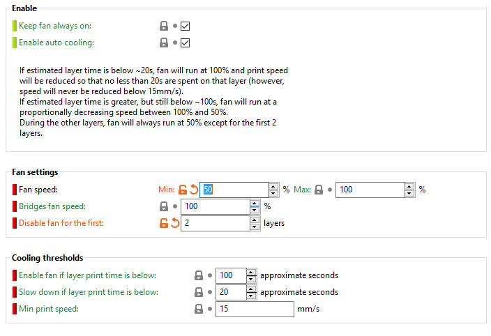
I’ve been generating a lot of print failures.

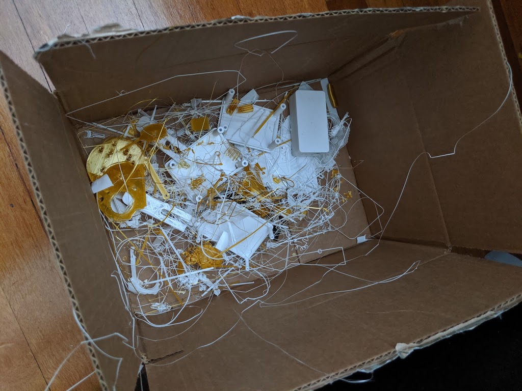
Mostly they show up on the first layer, but some happen much later on.

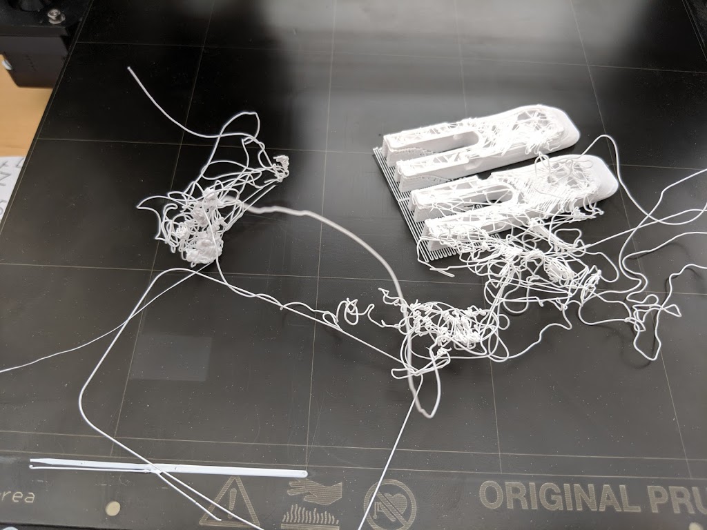
There seem to be some apparently random things going on.  The same print will work sometimes and not others.

Squish=0

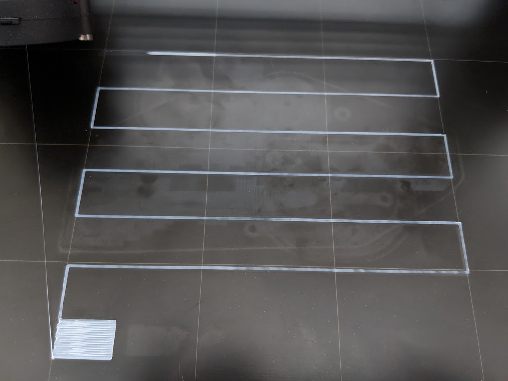
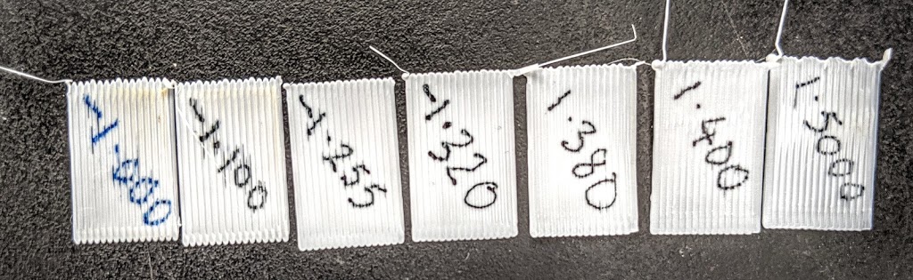
I repeated the First Layer Calibration tests for a whole bunch of different settings.  I wondered what would happen with squish=0

I marked the patch with the squishing factor.

The PLA hardly stuck to the bed, and so when the hot end changed direction it would pull up the recently deposited PLA and drag it to the new position.  The patch was clearly inadequate.  Well at least that all makes sense.

 
Squish=1.5

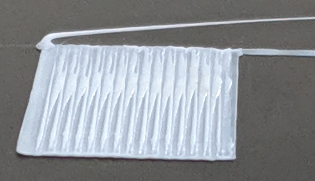
Notice how the PLA has become almost transparent in the zig-zag pattern.  It was pretty hard to remove too.  So I think this can be called “well attached”, but perhaps a little too attached?

Other squish factors

I looked end on at patches with different squish factors.


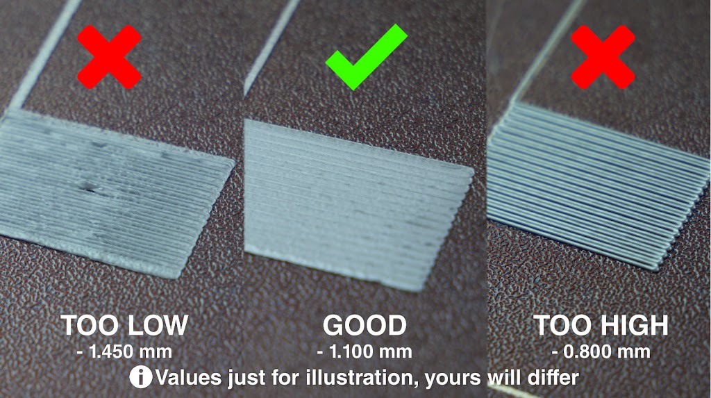
None of them looked like their diagram.

So then I looked at the faces of the patches.

 And their example…

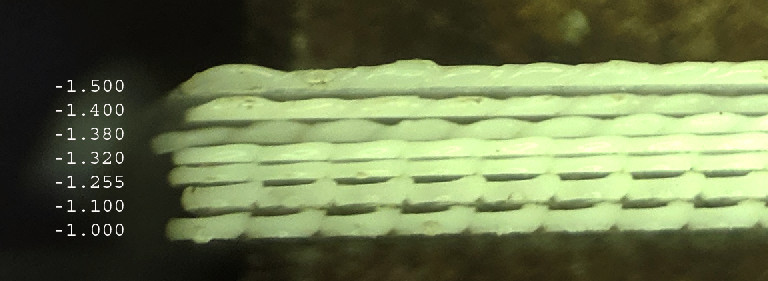
Ability to print right angles cleanly

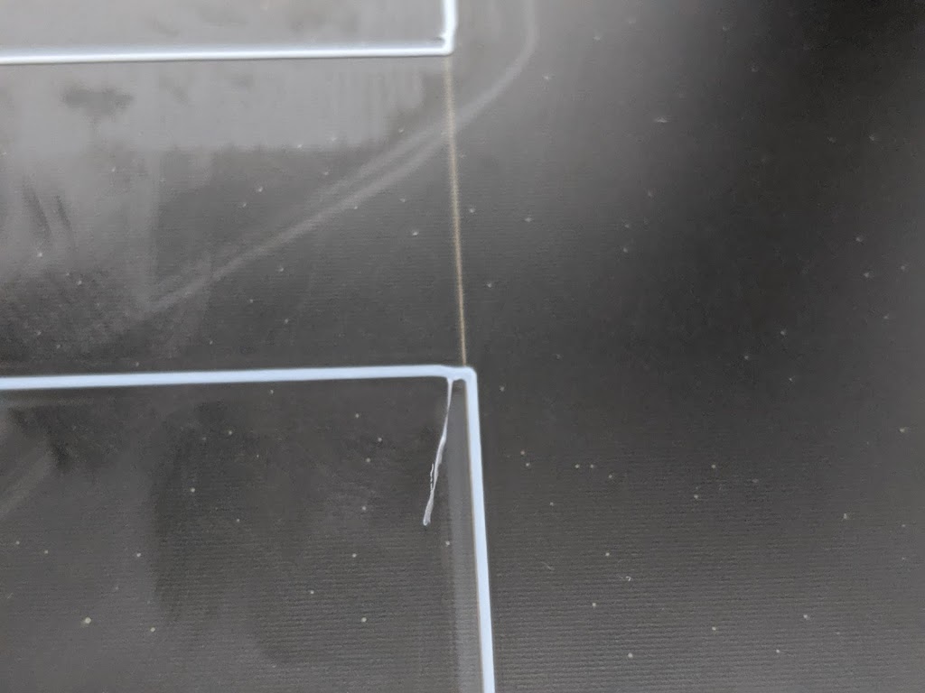
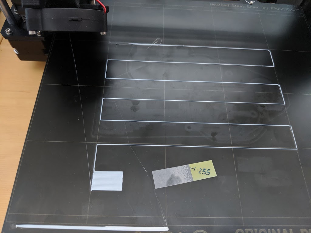
-1.255 is OK, but the corners are certainly rounded off

-1.4 produced decent corners

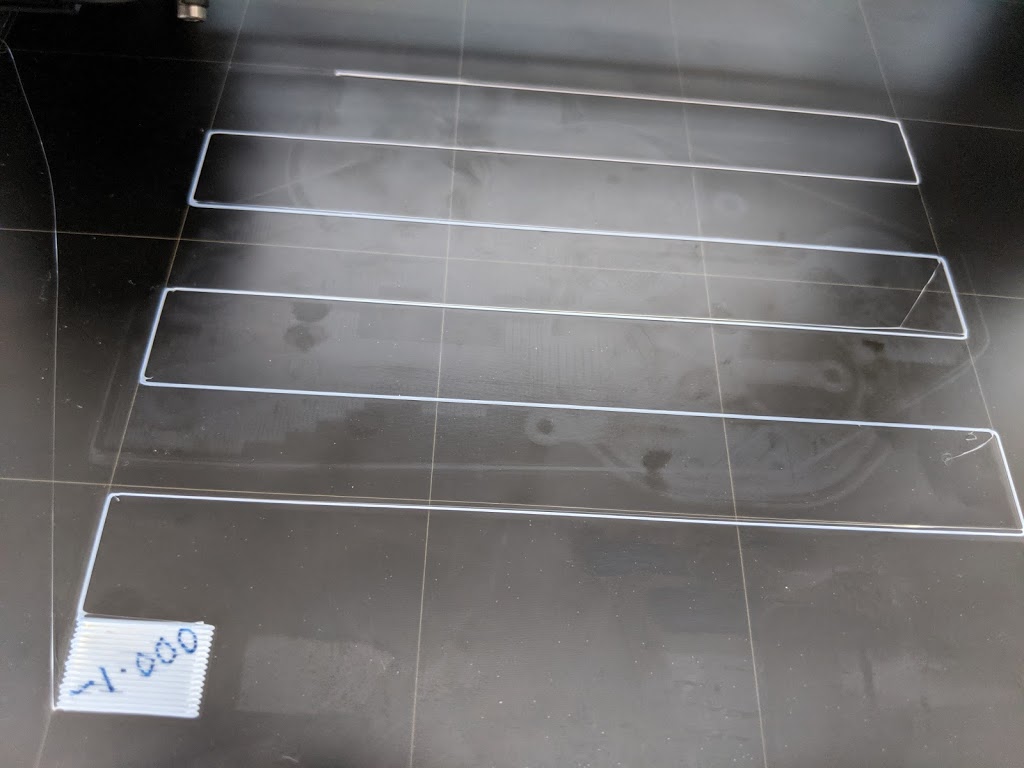
-1.000 produces rounded corners.
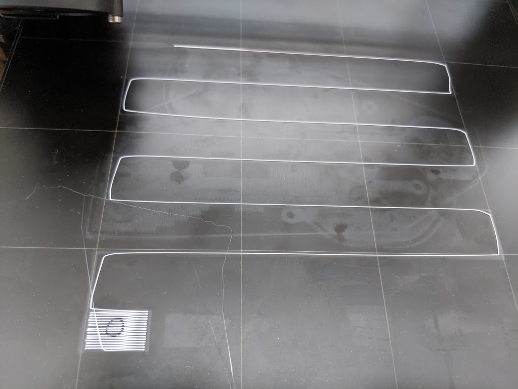
0.000 is a disaster as I’d expect
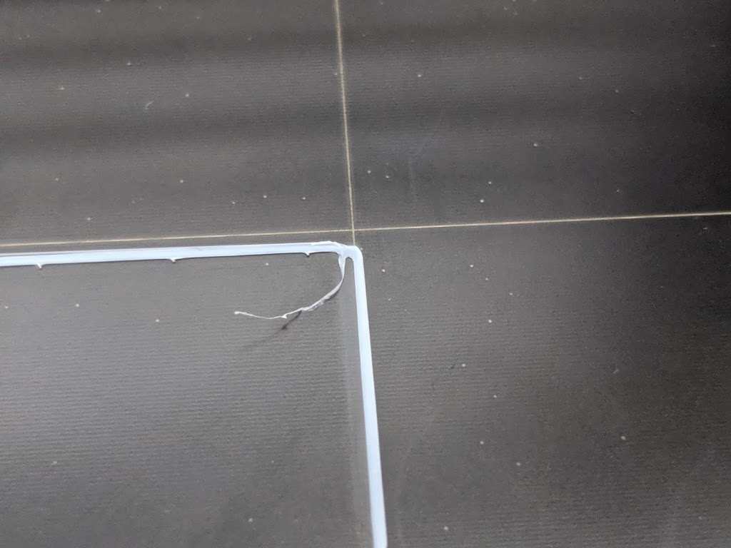
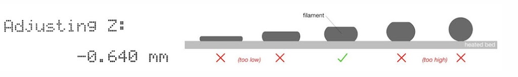
And the winner is:

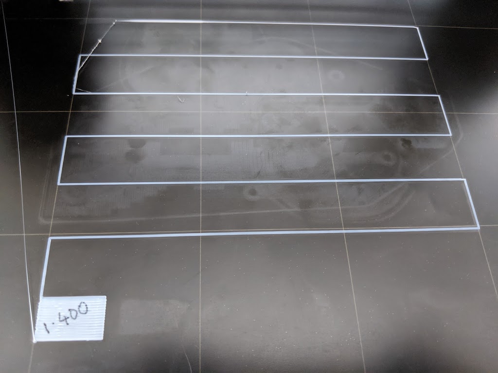
Well since I have to choose, I’d say the appearance of 1.38 is the best.

But the first layer still doesn’t stick all the time.

Acetone rocks

So I cleaned the sheet with acetone as they suggest.  It looked quite uniform afterwards, so I think I did manage to remove some residue.
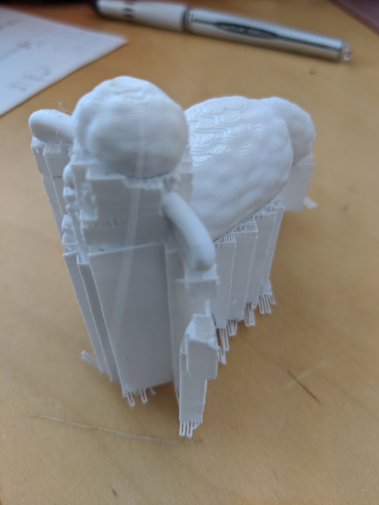
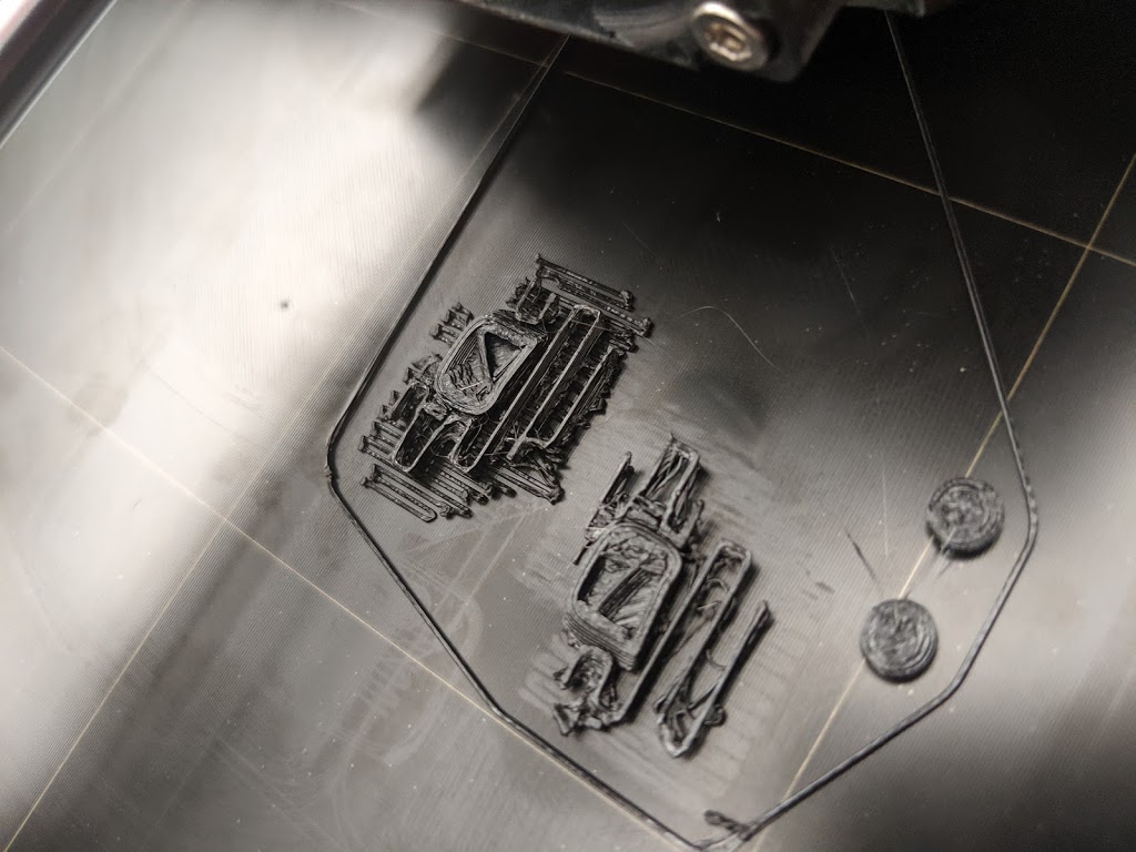
Next I printed the most recalcitrant object. with my 1.38 number.
And this time it stuck.  I’m not saying the result looks good!

Everything was printing OK until half-way through today, for no apparent reason I started getting “moth-eaten” prints.

I tried re-calibrating and squishing down a little more but it didn’t change a thing.   I cleaned the nozzle, and wiped the bed.  All the settings are as per normal.  What’s the problem?

Solution

I finally broke down and squished down a whole lot more, until I was getting perfect right angles at the corners of the “First layer calibration” pattern.  That subtracted an extra 0.12  mm from the bed, and seemed to improve things a lot.

But there are still apparently random things going on that I don’t yet understand.

I have installed my plant (senico radicans) monitor prototype.  Not quite finished yet but I want to see how well it works – if at all, before I decalre the boxes done.

The sensor is connected to the wireless relay which is powered by the solar cell.  The wires lead into the wireless relay via a couple of grommets.  I have not wired up the button/LED yet, and the holes are a little too close to the edge for comfort, so I might remake the cover.

The base station can be hundreds of yards away but it actually only about 4′ away.  It receives the moisture and battery data from the base station using LoRa wireless, and then relays it to https://www.lamming.com/cc, a simple cloud service, using WiFi and the internet.

The box didn’t print very evenly and has a noticeable band around the side.  Otherwise it turned out well.

I have a standard parametric box design that can be parameterized to handle any PCB.  The PCB is fixed to the base using screws that fit into nurled nuts that are hot-pushed into the plastic holes.  That works really well and is very simple to do.  I need to get some pan-head screws rather than these countersunk screws.

I need to find a better way to pass a USB cable through the plastic shell.  Have to look to see how the pros do it without a bunch more soldering of wires.

Base Station

The cloud service produces graphs that look like this:

I printed Shaun the Sheep.  The first attempt collapsed because there were no supports under his head and belly.

The next attempt included rafts, but added two hours to the print time.

Shaun with supports
It took about 15 minutes to carefully remove all the supports.  Many snapped off easily leaving little behind, but a few had to be cut off.  Then I had to file off the rough remains.

I finished the case for my base station.  I found an easy way to insert threaded nurled inserts into the plastic and then the PCBs can be attached with screws.

Incidentally, the base station receives LoRa packets from the sensor and posts them to the web using WiFi. 

The single button is for FOTA.  A single press on the recessed button/LED combo button requests it to go out the web and download my latest firmware.   It takes about 30s to load new firmware.

The socks David ordered arrived.  Blue and squishy,

It looks like it is pretty easy to fit it over the head without removing anything to do so – so I did.

Then I noticed that it wasn’t seating well.  On further inspection I discovered there was a lot of melted filament (technically known as “gunge”) stuck to the face of the heating block.  I turned the heat back on, and tried to wipe it off without burning my fingers.  I found that some slightly abrasive lens wipes were the most effective.  They are impregnated with alcohol which might have helped – I hope that’s not a bad thing.

FItted the boot and re-ran the TreeFrog – the one that failed with “Thermal Runaway” last time I ran it.  This time I used absolutely bog-standard parameters supplied by Prusa for Generic PLA.

As usual, the temp sank on layer two.  The temp for layer 2 is supposed to drop from 215 to 210.  In fact it dropped to 205 and then recovered in about a minute.  So far so good.

Issue

After each print quite a bit of gunge builds up around the sock hole and interferes with the next print.  Seems important to clean the sock off every 2/3 prints.

My first design didn’t print well, and there were a bunch of design snags I hadn’t quite appreciated.  It might be useful to figure out how to render a PCB in 3D so I can see how it fits before printing.

My second design came out a lot better.

The lid clicks on and off, and holds pretty tight (I have to use a spudge to get it off).  The retaining lips seem to flex just the right amount and don’t snap off!

The antenna and illuminated button fitted quite tightly.  The USB plug fits tight in the hole – perhaps a bit to tightly.  Obviously I have a bit more soldering to do!


I decided to mount the PCB using nurled captive nuts that I could push into the plastic.  I used the tip of the soldering iron to heat them up and push them in.  It was surprisingly easy.  I have used countersunk screws in this image because that’s all I had to hand.

Printing Parameters

I finally managed to reliably print stuff.  There seemed to be two issues:

I was using the FAST filament setting and this was certainly faster!  It simply didn’t print the last 10%.

When I changed to the 0.15 OPTIMAL settings things got a lot better.

I also followed David’s advice and set the temp lower except for the first two layers.

Temperature

After the first layer the fan turns on and drops the temp so low that it generates a “Thermal Runaway” error.  I changed the params as follows and got a better result

Partial printing

A couple of attempts resulted in prints that stopped short of producing a finished print.  I changed the printing quality to “0.15 OPTIMAL” and that seemed to fix that problem.