I need to be able to build different versions of my code, one for debugging and one for “release”, for example.

The standard mechanism for doing this is to define, or leave undefined, various symbols that cause the compiler to include, or exclude chunks of source code.  The symbols are not in the code, but are submitted to the compiler when it is called.   So called the compiler with the flag -Drelease inserts a symbol called “release” in the compiler’s symbol table before it gets started.  Then during compilation the compiler can conditionally switch in, or out, chuncks of code based on whether this is “release” code or not.

Eclipse works this way too – only it doesn’t.

Here is a very simple program, to illustrate my vexing issue.   My conditional compilation variable is called “FOO”

The program is silly, and is designed to fail during compilation if x=0.  (If x=0 the compiler will detect that the program is null, and will signal a compiler error.)
The important part is at the top.   It says that if a symbol called FOO has been previously defined then the compiler should compile the statement “int x = 1”, and if FOO is not defined it should instead compile the statement “int x = 0”.
Elsewhere in the property definitions for this program I have defined FOO.   
Eclipse kindly grays out the code that it is going to ignore.  In this example something has gone wrong because Eclipse implies that x=1, but the compilation fails (little yellow exclamation mark) because clearly x=0.
Whatever I do, I get the compiler error.   What a time-waster Eclipse is!


We have had issues getting the debugger to work.  I discovered that it wasn’t so much that the connections were wrong, as Eclipse being very finicky.

When it falls into a trap before getting to main, it can be because: the code is expecting SEMIHOSTING, but gdb is not ready to catch.  If semi-hosting libraries are used in the firmware, then semi-hosting must be enabled in gdb.

Put another way, code will simply fail to start (trap at 0x0) if semi-hosting apparatus is not physically set up.

The following has to be  setup exactly right for semi-hosting to work:
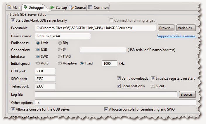
If it hits a trap at 0x0 then there is no trap handler for semi-hosting, or there is no code loaded.

If the code should hit a breakpoint, but simply starts automatically, then it is perhaps because debugging has not been specified to the compiler, and it is not generating the debug handles.  It ought to look like this:

If user-breakpoints are being skipped then it might be because the code has been optimized away.  Turn all optimization off like this:

If it hits the breakpoint at main, but the source doesn’t show up then it probably failed to load the symbols from the elf file.   The spec should look like this.

If there are incorrect load symbol files, or no load symbol files specified, or the file names don’t look like the above, then close this dialog, close the project, re-open it, and refresh the projects and then see if the right file names are turning up.

To remove semihosting the following has to be done:

  1. Remove the defined constants
    DEBUG_NRF_USER
    DEBUG
  2. Remove the other linker flags: -mabi=aapcs –specs=rdimon.specs -Wl,–start-group -lgcc -lc -lc -lm -lrdimon -Wl,–end-group
  3. Clear these check boxes
    and on the previous “debugger” tab: 

I have found a version of the Segger tools that appears to simply offer flashing, and erasing.

https://www.segger.com/jlink-software-beta-version.html

It’s an executable that should be moved to the desktop, I guess.  When installed the icon looks like this.
Run it.
Set the Device to nRF51822_xxAA
Set the Interface to SWD
Click OK
To erase the chip press (you guessed it) Erase Chip
To program with a hex file, browse to find the hex file.

and press Program Device

I don’t know if this is any help but I tried to figure out the correspondence between the nRF51822 pins, and the RayTac module pins.   I am assuming that we are using the DC/DC schematics for our situation, but I’m not confident about that, and so this may all have been a waste of time.  
I did my analysis by writing a non-EE description of what was connected to each pin in each schematic.  Then I tried to line-up the descriptions and look for the obvious fits, and non-fits.  If I had a schematic of the internals of the RayTac module, maybe I could find more fits.  There were several puzzling (to me) things:
The executive summary of my findings:
  1. The RayTac module uses XL1/XL2 and not XC1/XC2.
  2. RayTac pin 3 and nRF51822 pins 35+36 use different capacitors.
  3. I think many pins are internally connected to ground and so they don’t appear on the module.

Connections to nRF51822 for DC/DC operations according to Nordic
Connections to RayTac module for DC/DC operations, according to RayTac

I think I have made a grave mistake.

Previously I connected the EVB1000 board to the Segger using a squid cable.  I managed to program it just fine.

Today I connected the EVB1000 to the SEGGER using the ribbon cable, making sure to connect it the right way around.  The pinout seemed identical.  The SEGGER responded, but the board didn’t.

So I connected the squid cable back and it communicated and loaded code, which is good, but puzzling

But now the DW1000 chip won’t answer the SPI line.   Have I blown up another one?

I think it was because I had connected the ribbon cable instead of the squid (and that’s the most likely reason). After pondering, maybe that 5V supply pin on the SEGGER ribbon is a bad idea? But last week I was trying to hook up the DW1000 SPI lines, and I wonder if they might be super-sensitive?

http://www.mymodernmet.com/profiles/blogs/cicret-bracelet

At first glance, a cool idea.   I wonder if it works in daylight?  Battery life?

I can’t see how they can make it work in practice, but it is a nice idea. I looked carefully at the pics, and they smell of Photoshop to me because all the text appears sharp in all pictures, yet the projection is onto an unpredictably uneven surface, but the depth of focus appears perfect all the time.

Yesterday David gave me the new TS06.2 board.    Today I tried to figure out the connections and talk to it.

After fiddling around for a long while, I couldn’t get it to respond.   Then I discovered that one wire was in the wrong place.
But that still wasn’t enough.  So I emailed David.  I checked a bunch of connections under the scope.  

I reckon that all my fiddling has blown the module up somehow.

Having has a lack of joy with the TS06.2 I realized that it was important for David to be able to test the hardware too.   It would be good if I can make test programs and squirt them down the line to his house to poke at.

So yesterday I set up a spare laptop with a basic development environment so he could test the software.

At “Mimis” today David discovered that a couple of the jLink wires were crossed and with penknife and other stuff we happened to have in our pockets D fiddled it.

Although the jLink was now able to talk to the Nordic, and could apparently flash code into it, the code would not execute.   I’m now even more sure I have blown up the module.

The next step is to find a free sharable repository where we can exchange our code.

How do you flash about the S130?
The newer J-link drivers requires more ram for the flash algorithm which is unfortunately not increased automatically, hence the error in your log file.  Please see attached screen shot of the correct flash configuration. This should let you flash directly from the IDE.

ALSO

Flashing binary (*.bin) files is possible with J-Link Commander.
Just start it the following way:

JLink.exe -if SWD -device nRF51822 -speed 4000

Then type:
J-Link>r
J-Link>loadbin <Path>,<DownloadAddr>