The Bus Pirate board allows you to look at I2C/SPI and other signals in a convenient way.
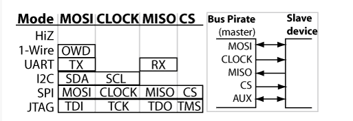
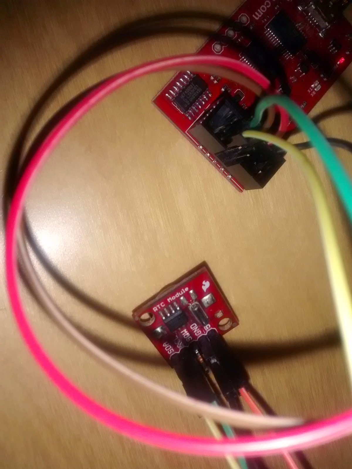
Connections

Pull-up resistorsI2C is an open-collector bus, it requires pull-up resistors to hold the clock and data lines high and create the data ‘1’. I2C parts don’t output high, they only pull low, without pull-up resistors there can never be a ‘1’. This will cause common errors such as the I2C address scanner reporting a response at every address. Read more about open collector/open drain bus types, and the Bus Pirate’s on-board pull-up resistors.

The figure outlines the basic parts of the Bus Pirate v2go on-board pull-up resistors. A pull-up (or pull-down) voltage supplied through the Vpullup (Vpu) pin is fed into a CD4066 analog switch (IC3). The 4066 distributes the pull-up voltage to four 10K resistors (R20-23) that connect to the MOSI, CLOCK, MISO, and CS bus pins.
Continue reading our practical guide to the Bus Pirate v2go’s pull-up resistors after the break.
I2C>v <<< voltage monitor reportVOLTAGE MONITOR: 5V: 5.0 | 3.3V: 3.3 | VPULLUP: 5.0 |
I2C>
You must connect the Vpullup pin to a voltage. The pull-up resistors aren’t hard-wired to a power supply, you can apply any voltage level that’s needed (from ground to +5volts). Type ‘V’ in the Bus Pirate terminal to see the current voltage on the Vpullup pin.
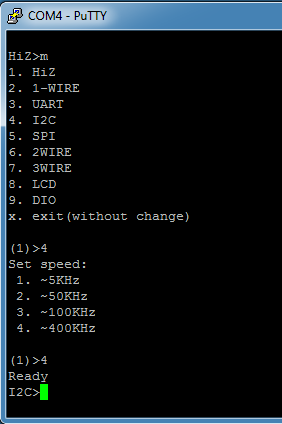
Talking to it from Putty

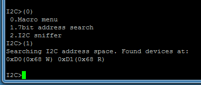

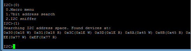
Sniffing I2C bus of the TS05b