I’m working on getting serial IO working on our TS06.1.
I have read up about Serial Wire Debug. I have set up the interface so it ought to work, and managed to implement code to drive that interface, but it just doesn’t work.
I think it has to be something to do with the missing SWO pin.
This blog post seems to indicate it isn’t possible. However it does hint at an alternative method.
Does anyone know how to get debug messages out to host console via SWD? I know SWD supports Serial Wire Viewer, but not sure how to get it working over GDB with JLink.
I am using: nRF51822 ARM GCC toolchain OSX
Thanks,
Chris
Doesn’t that require SWO to be implemented? (Which is not on the Nordic part). I would tend to think that Nordic wouldn’t have piped the serial port through the Segger on the eval kit if there was a proper SWV/SWO implementation :) -m
Marc Nicholas (Sep 26 ’13)convert to answer
I have read up about Serial Wire Debug. I have set up
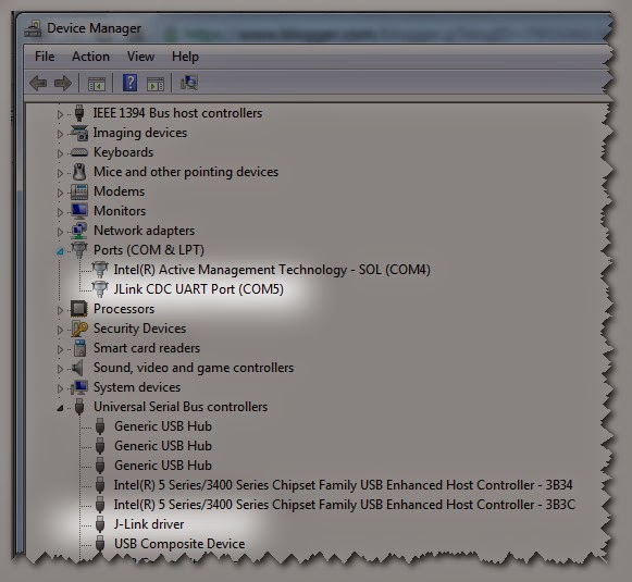
O jeez, I can’t believe this. Communication with the UART has been there all along. I don’t know where it is written down – one of those myriad of “beware of the panther” documents I guess. On the devkit board you simply connect to the same COM port as the SEGGER uses itself. The clue is that when you plug in the DevKit two devices appear in the Device Manager. The JLink USB driver of course, but also a special CDC(?) UART driver on a COM port.

So that’s how the devkit does it, so now, how do I get to do it via the SEGGER?
When I plug in the SEGGER, I notice that I get a JLink driver, and a new COM8 port, but of course the com port doesn’t work. I guess that’s because our hardware doesn’t route that pin through the SEGGER. So how should it be routed?
The schematic for the devkit board PCA10001 shows some connections going from the nRF51822 P0.08-P0.11 (UART, rts,txd,cts,rxd) to the SEGGER pins 38-41 (CTS/RxD/RTS/TxD). Now the question is: where do these present themselves on the JLink-EDU?
Is there a schematic for the JLink EDU.
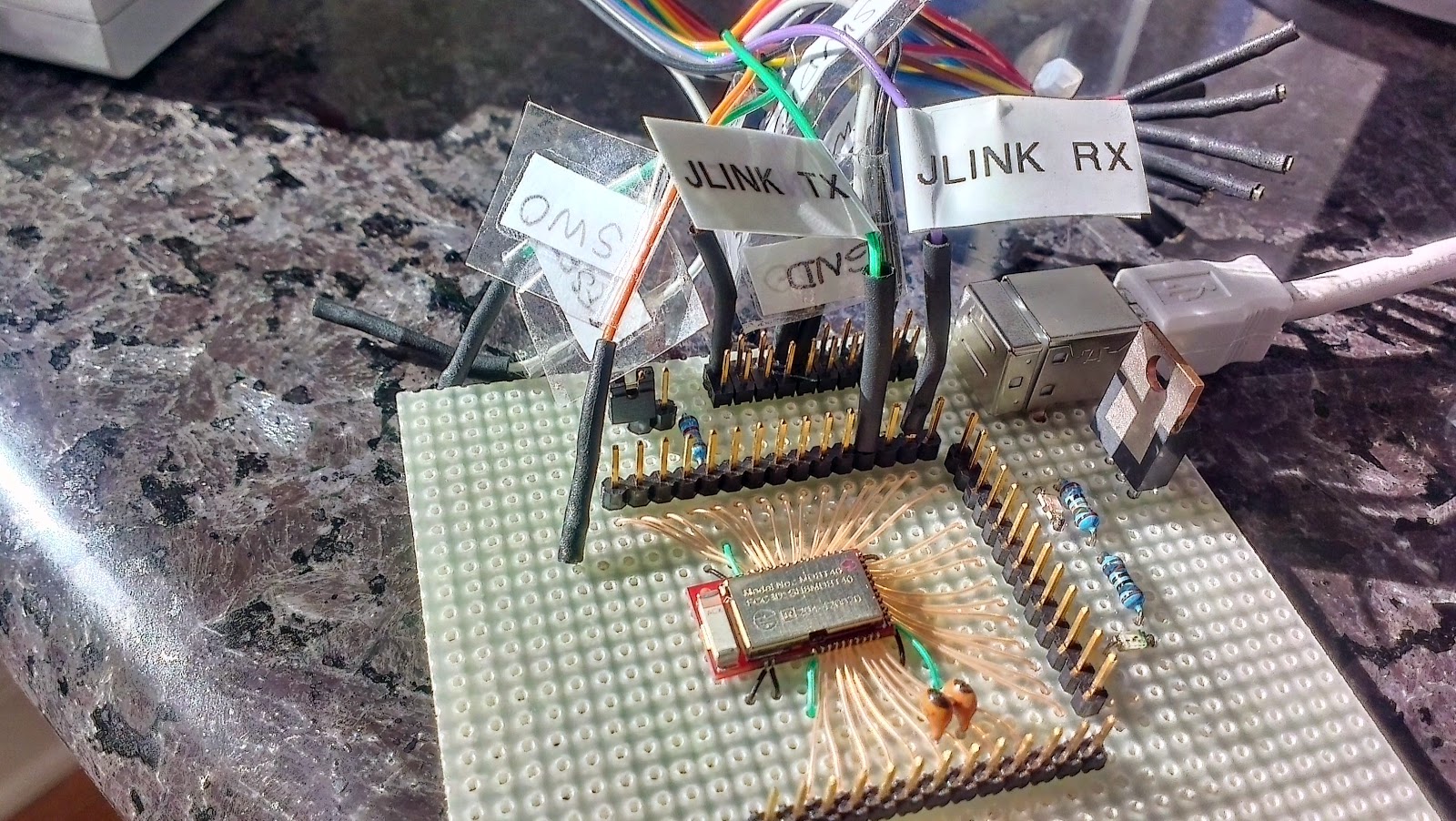
P279 of J-Link / J-Trace User Guide, Software Version V4.86 Manual Rev. 2 Document: UM08001, Date: June 6, 2014 shows this diagram.

I’m not sure this is the right document but it seems pretty relevant. It seems to suggest that pins 17 and 5 should be connected as follows:
JLINK TX 5 -> P0.11 RxD
JLINK RX 17 <- P0.09 TxD
Nada… Ah, it has hardware flow-control turned on, I’ll turn it off..
Yay.
It works. There’s some screwy characters at the start that I don’t understand, but I expect that’s some configuration issue, but it does echo characters.