I am pursuing two lines of inquiry as to why Nordic serial data is displayed as incorrect (junk) characters on the laptop. Theory 1 is that the bits are in the wrong order; Theory 2 is that the voltage levels are incorrect.
Bit Order
I can’t believe that after all these years I don’t know this. It seems such a very basic thing, but now that I am poking around I find that very few people seem to know the truth.
So given the scope data, I had the same thoughts. It looked like the bits were reversed, which is why I took a picture or 0x80 and 0x01. To be honest I thought I remembered that serial data was always sent most significant bit (MSB) first, but this seemed to show LSB first. To be sure I googled RS232 bit order and saw this.
The diagram and the text are not explicit about the bit order. By that I mean, is the chracter in the above example 0x51 = ‘Q’, or reading in the opposite direction 0x8a =
Š (Latin capital letter S with caron). The latter seemed an unlikely choice for this example, which implies MSB-first is more likely.
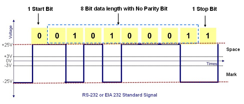
The serial port has many pins. We will discuss the transmit and receive pin first. Electrically speaking, whenever the serial port sends a logical one (1) a negative voltage is effected on the transmit pin. Whenever the serial port sends a logical zero (0) a positive voltage is effected. When no data is being sent, the serial port’s transmit pin’s voltage is negative (1) and is said to be in aMARK state. Note that the serial port can also be forced to keep the transmit pin at a positive voltage (0) and is said to be the SPACE or BREAK state. (The terms MARK and SPACE are also used to simply denote a negative voltage (1) or a positive voltage(0) at the transmit pin respectively).When transmitting a byte, the UART (serial port) first sends a START BIT which is a positive voltage (0), followed by the data (general 8 bits, but could be 5, 6, 7, or 8 bits) followed by one or two STOP BITs which is a negative(1) voltage. The sequence is repeated for each byte sent.
But then this article seemed to be explicit, though we don’t know the authority of the source. Obviously it makes sense to look at the official RS232 specification which I anticipate is inpenetrable. The article says:
Assume we want to send the letter ‘A’ over the serial port. The binary representation of the letter ‘A’ is 01000001. Remembering that bits are transmitted from least significant bit (LSB) to most significant bit (MSB), the bit stream transmitted would be as follows for the line characteristics 8 bits, no parity, 1 stop bit, 9600 baud.
LSB (0 1 0 0 0 0 0 1 0 1) MSB
So that suggests that it is indeed LSB first with optional parity and stop-bit. So my bits would seem to be reversed. This seems pretty unlikely huh?
Here for comparison is my scope image of ‘A’ allegedly with even parity.
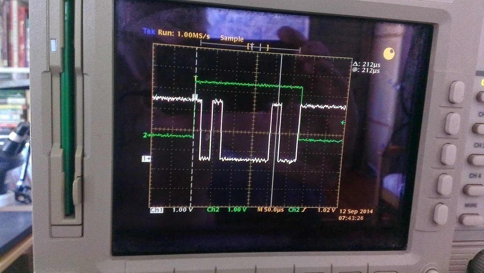 |
| Character ‘A’ |
 |
| Character ‘C’ |
Voltage
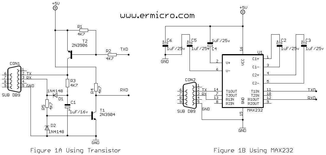
So now onto my second line of attack. The example code from Nordic seems to suggest that it is OK simply to connect the output of the Nordic Tx GPIO to the input of the laptop serial. I have done that, and used both a genuine serial port, and a USART->USB converter – the latter on both laptops. To the extent that I can see, I get exactly the same results – junk.
My bits appear to be about 2.7 volts peak to peak, and the standard suggests that +25 to -25 is the required level, for which I’d need some sort of level shifter, like a MAX232 chip. But that flies in the face of what they imply in the Nordic example.
More investigation required.