I started to persuade the ARM chip to emit characters out its UART. I connected the output of the ARM UART to the UART on my PC and after some fiddling around… didn’t get a thing.
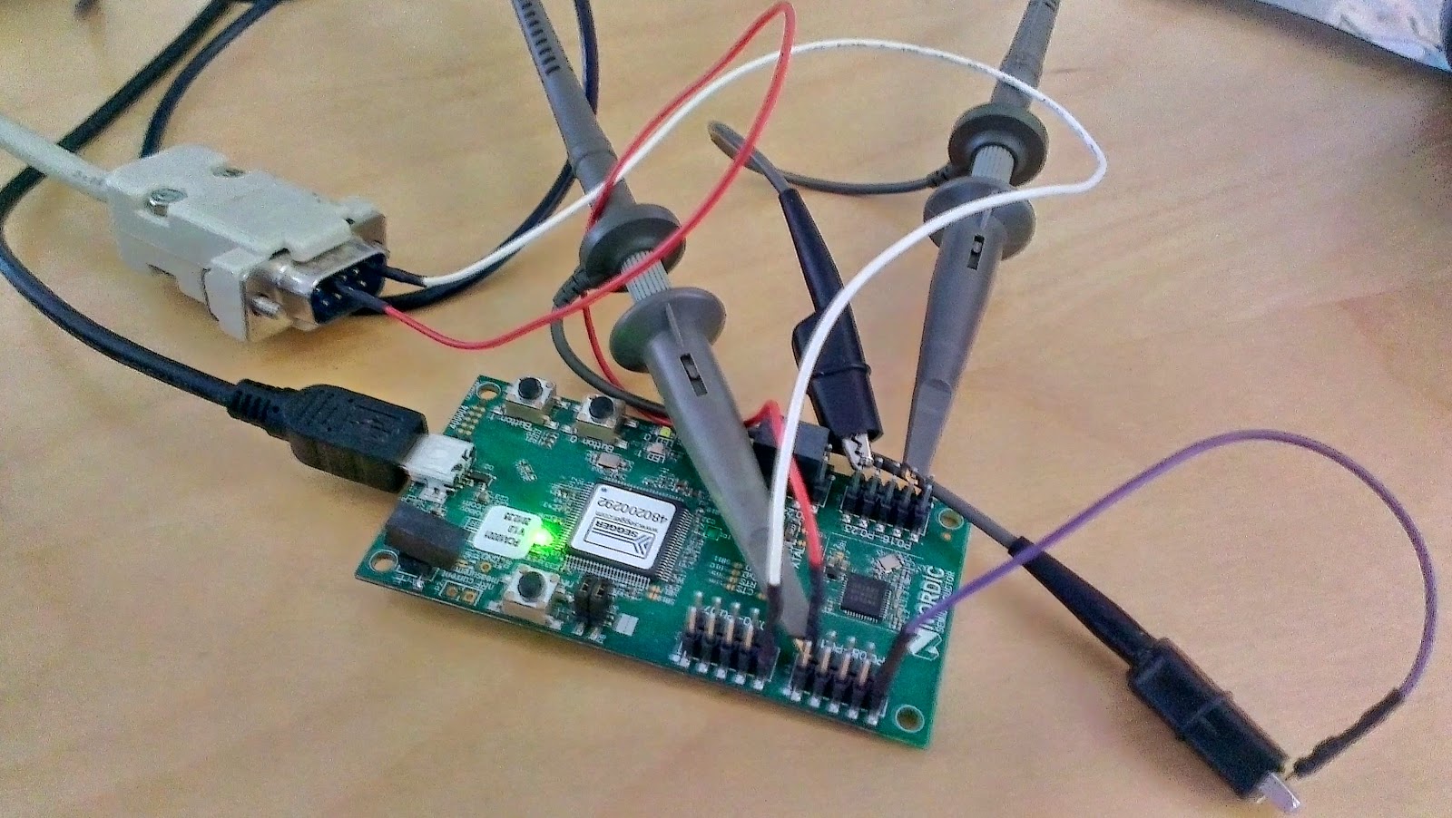 |
| Connections to laptop and scope |
First issue, there isn’t a serial port on my new laptop. Had to dig out my old USB->Serial cable. Then of course none of the drivers work.
Still nothing, but then I discovered I was monitoring the wrong pin. OK.. progress! There is stuff coming out. But it’s garbage.
Here’s what it says in the documentation for the Nordic UART example program.
The UART Example demonstrates basic UART usage for communicating with a PC terminal. It transmits and receives data through the configured pins as a serial device. The configure pins needs to be redirected to a COM port (terminal programs like putty can listen to this COM port through a terminal session). When the program starts it will transmit “START: ” through this serial device usingsimple_uart_putstring and this should be visible on the terminal. All typed characters on this terminal will be transmitted to the program through simple_uart_get and when an exit character ‘q’ or ‘Q’ is typed the program will end into an infinite loop after transmitting “EXIT!” on a new line of the terminal.
Tried all the usual things, baud rate, stop bits, parity… still garbage.
Now I dragged out the ‘scope. Used one of the LED pins as a trigger. I made a program that outputs all characters from 0..127 at 100ms intervals.
simple_uart_config(RTS_PIN_NUMBER, TX_PIN_NUMBER, CTS_PIN_NUMBER, RX_PIN_NUMBER, HWFC); // hardware flow-control = false
nrf_gpio_cfg_output(ERROR_PIN);
while (true)
{ for (b=0; b<127; b++)
{
nrf_gpio_pin_write(ERROR_PIN, 1); // trigger for scope
simple_uart_put(b);
nrf_gpio_pin_write(ERROR_PIN, 0);
nrf_delay_us(1000*100); // a respectable pause
}
}
The scope showed the bits coming out like this. i.e. a byte value of 0x01 actually appears on the scope like this.
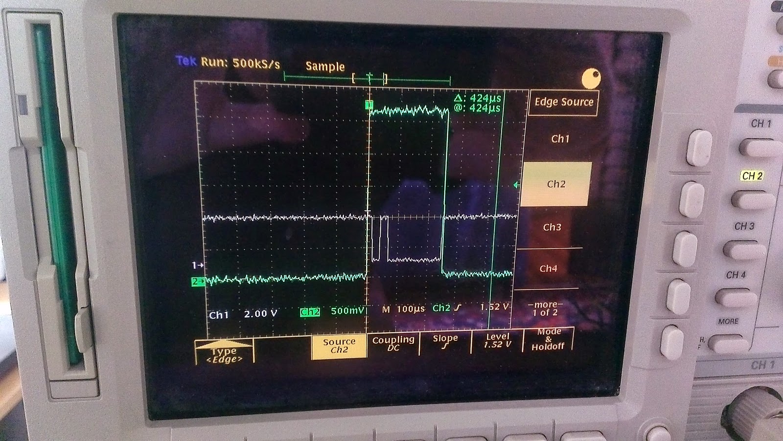 |
| Character code 0x01 (no parity bit) |
 |
| Character code 0x80 (no parity bit) |
Now the PC has decided that it won’t listen to the USB->UART COM any more.